Thickness Measurements of Thin Material
Eddy current techniques can be used to perform a number of dimensional measurements. The ability to make rapid measurements without the need for couplant or, in some cases even surface contact, makes eddy current techniques very useful. The type of measurements that can be made include:
● thickness of thin metal sheet and foil, and of metallic coatings on metallic and nonmetallic substrate
● cross-sectional dimensions of cylindrical tubes and rods
● thickness of nonmetallic coatings on metallic substrates
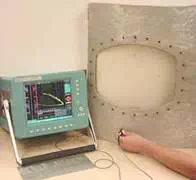
Corrosion Thinning of Aircraft Skins
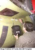
One application where the eddy current technique is commonly used to measure material thickness is in the detection and characterization of corrosion damage on the skins of aircraft. Eddy current techniques can be used to do spot checks or scanners can be used to inspect small areas. Eddy current inspection has an advantage over ultrasound in this application because no mechanical coupling is required to get the energy into the structure. Therefore, in multi-layered areas of the structure like lap splices, eddy current can often determine if corrosion thinning is present in buried layers.
Eddy current inspection has an advantage over radiography for this application because only single sided access is required to perform the inspection. To get a piece of film on the back side of the aircraft skin might require removing interior furnishings, panels, and insulation which could be very costly. Advanced eddy current techniques are being developed that can determine thickness changes down to about three percent of the skin thickness.
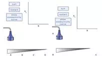
Thickness Measurement of Thin Conductive Sheet, Strip and Foil
Eddy current techniques are used to measure the thickness of hot sheet, strip and foil in rolling mills, and to measure the amount of metal thinning that has occurred over time due to corrosion on fuselage skins of aircraft. On the impedance plane, thickness variations exhibit the same type of eddy current signal response as a subsurface defect, except that the signal represents a void of infinite size and depth. The phase rotation pattern is the same, but the signal amplitude is greater. In the applet, the lift-off curves for different areas of the taper wedge can be produced by nulling the probe in air and touching it to the surface at various locations of the tapered wedge. If a line is drawn between the end points of the lift-off curves, a comma shaped curve is produced. As illustrated in the second applet, this comma shaped curve is the path that is traced on the screen when the probe is scanned down the length of the tapered wedge so that the entire range of thickness values are measured.
When making this measurement, it is important to keep in mind that the depth of penetration of the eddy currents must cover the entire range of thicknesses being measured. Typically, a frequency is selected that produces about one standard depth of penetration at the maximum thickness. Unfortunately, at lower frequencies, which are often needed to get the necessary penetration, the probe impedance is more sensitive to changes in electrical conductivity. Thus, the effects of electrical conductivity cannot be phased out and it is important to verify that any variations of conductivity over the region of interest are at a sufficiently low level.
Measurement of Cross-sectional Dimensions of Cylindrical Tubes and Rods
Dimensions of cylindrical tubes and rods can be measured with either OD coils or internal axial coils, whichever is appropriate. The relationship between change in impedance and change in diameter is fairly constant, except at very low frequencies. However, the advantages of operating at a higher normalized frequency are twofold. First, the contribution of any conductivity change to the impedance of the coil becomes less important and it can easily be phased out. Second, there is an increase in measurement sensitivity resulting from the higher value of the inductive component of the impedance. Because of the large phase difference between the impedance vectors corresponding to changes in fill-factor and conductivity (and defect size), simultaneous testing for dimensions, conductivity, and defects can be carried out.
Typical applications include measuring eccentricities of the diameters of tubes and rods and the thickness of tube walls. Long tubes are often tested by passing them at a constant speed through encircling coils (generally differential) and providing a close fit to achieve as high a fill-factor as possible.
An important application of tube-wall thickness measurement is the detection and assessment of corrosion, both external and internal. Internal probes must be used when the external surface is not accessible, such as when testing pipes that are buried or supported by brackets. Success has been achieved in measuring thickness variations in ferromagnetic metal pipes with the remote field technique.
Thickness Measurement of Thin Conductive Layers
It is also possible to measure the thickness of a thin layer of metal on a metallic substrate, provided the two metals have widely differing electrical conductivities (i.e. silver on lead where s= 67 and 10 MS/m, respectively). A frequency must be selected such that there is complete eddy current penetration of the layer, but not of the substrate itself. The method has also been used successfully for measuring thickness of very thin protective coatings of ferromagnetic metals (i.e. chromium and nickel) on non-ferromagnetic metal bases.
Depending on the required degree of penetration, measurements can be made using a single-coil probe or a transformer probe, preferably reflection type. Small-diameter probe coils are usually preferred since they can provide very high sensitivity and minimize effects related to property or thickness variations in the underlying base metal when used in combination with suitably high test frequencies. The goal is to confine the magnetizing field, and the resulting eddy current distribution, to just beyond the thin coating layer and to minimize the field within the base metals.