Surface Crack Detection Using Sliding Probes
Many commercial aircraft applications involve the use of multiple fasteners to connect the multi-layer skins. Because of the fatigue stress that is caused by the typical application of any commercial aircraft, fatigue cracks can be induced in the vicinity of the fastener holes. In order to inspect the fastener holes in an adequate amount of time, sliding probes are an efficient method of inspection.
Sliding probes have been named so because they move over fasteners in a sliding motion. There are two types of sliding probes, fixed and adjustable, which are usually operated in the reflection mode. This means that the eddy currents are induced by the driver coil and detected by a separate receiving coil.
Sliding probes are one of the fastest methods to inspect large numbers of fastener holes. They are capable of detecting surface and subsurface discontinuities, but they can only detect defects in one direction. The probes are marked with a detection line to indicate the direction of inspection. In order to make a complete inspection there must be two scans that are orthogonal (90 degrees) to each other.
Probe Types
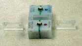
Fixed Sliding Probes
These probes are generally used for thinner material compared to the adjustable probes. Maximum penetration is about 1/8 inch. Fixed sliding probes are particularly well suited for finding longitudinal surface or subsurface cracks such as those found in lap joints. Typical frequency range is from 100 Hz to 100 kHz.
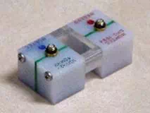
Adjustable Sliding Probes
These probes are well suited for finding subsurface cracks in thick multi-layer structures, like wing skins. Maximum penetration is about 3/4 inch. The frequency range for adjustable sliding probes is from 100 Hz to 40 kHz.
Adjustable probes, as the name implies, are adjustable with the use of spacers, which will change the penetration capabilities. The spacer thickness between the coils is normally adjusted for the best detection. For tangential scans or 90 degree scanning with an offset from the center, a thinner spacer is often used.
The spacer thickness range can vary from 0 (no spacer) for inspections close to the surface and small fastener heads to a maximum of about 0.3 inch for deep penetration with large heads in the bigger probe types. A wider spacer will give more tolerance to probe deviation as the sensitive area becomes wider but the instrument will require more gain. Sliding probes usually penetrate thicker materials compared to the donut probes.
Reference Standards
Reference/calibration standards for setup of sliding probes typically consist of three or four aluminum plates that are fastened together within a lap joint type configuration. EDM notches or naturally/artificially- induced cracks are located in the second or third layer of the standard.
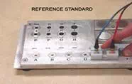
Reference standards used should be manufactured from the same material type, alloy, material thickness, and chemical composition that will be found on the aircraft component to be inspected. Sizes and tolerances of flaws introduced in the standards are usually regulated by inspection specifications.
Inspection Variables
Liftoff Signal Adjustment
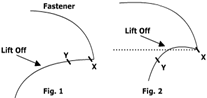
Liftoff is normally adjusted to be relatively horizontal. The term "relatively horizontal" is used here because the liftoff signal often appears a curved line rather than a straight line. Sometimes liftoffcan be a sharp curve and may need to be adjusted to run slightly upwards before moving downwards. See Figures 1 and 2.
Scan Patterns
A typical scan is centralized over the fastener head and moves along the axis of the fastener holes. This scan is generally used to detect cracks positioned along the axis of the fastener holes. For detecting cracks located transverse or 90 degrees from the axis of the fastener holes, a scan that is 90 degrees from the axis of the fastener holes is recommended.
Signal Interpretation
When the probe moves over a fastener hole with a crack, the indication changes and typically will create a larger vertical movement. The vertical amplitude of the loop depends on the crack length, with longer cracks giving higher indications.
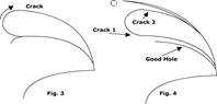
If the crack is in the far side of the fastener, as the probe moves over it, the dot will follow the fastener line first but will move upwards (clockwise) as it goes over the crack. If the crack is in the near side, it will be found first and the dot will move along the crack level before coming down to the fastener level.
If two cracks on opposite sides of the fastener hole are present, the dot will move upwards to the height by the first crack length and then come back to the fastener line and balance point. If the second crack is longer than the first one, the dot will move even higher and complete the loop (clockwise) before going down to the balance point. See Figures 3 and 4.
Probe Scan Deviation
Most probes are designed to give a narrow indication for a good fastener hole so that the loops from the cracks are more noticeable. Some probes and structures can give wider indications and a similar result can be obtained if the probe is not straight when it approaches the fastener. It is important to keep the probe centralized over the fastener heads. Doing this will give you a maximum indication for the fastener and a crack.
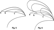
If the probe deviates from the center line, the crack indication will move along the loop that we saw in Figure 5 and is now present in Figure 6. The crack indication is at "a" when the probe is centralized and moves toward "b" as it deviates in one direction, or "c" as it deviates in the opposite direction. Point "b" gives an important indication even if it loses a small amount of amplitude it has gained in phase, giving a better separation angle. This is because we deviated to the side where the crack is located.
Crack Angle Deviation
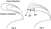
A reduction in the crack indication occurs when the crack is at an angle to the probe scan direction. This happens if the crack is not completely at 90 degrees to the normal probe scan or changes direction as it grows. Both the fixed and adjustable sliding probes are capable of detecting cracks up to about 30 degrees off angle. See Figures 7 and 8.
Electrical Contact
When inspecting fasteners that have just been installed or reference standards that have intimate contact with the aluminumskin plate, it is not unusual to obtain a smaller than normal indication. In some extreme cases, the fastener indication may disappear almost completely. This is due to the good electrical contact between the fastener and the skin. This condition allows the eddy currents to circulate without encountering a boundary, and therefore, no obstacle or barrier. Because of this effect, it is recommended to paint the holes before fastener installation.