Impedance
Electrical Impedance (Z), is the total opposition that a circuit presents to alternating current. Impedance is measured in ohms and may include resistance (R), inductive reactance (XL), andcapacitive reactance (XC). However, the total impedance is not simply the algebraic sum of the resistance, inductive reactance, and capacitive reactance. Since the inductive reactance and capacitive reactance are 90o out of phase with the resistance and, therefore, their maximum values occur at different times, vector addition must be used to calculate impedance.
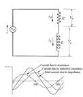
In the image below, a circuit diagram is shown that represents an eddy current inspection system. The eddy current probe is a coil of wire so it contains resistance and inductive reactance when driven by alternating current. The capacitive reactance can be dropped as most eddy current probes have little capacitive reactance. The solid line in the graph below shows the circuit's total current, which is affected by the total impedance of the circuit. The two dashed lines represent the portion of the current that is affected by the resistance and the inductive reactance components individually. It can be seen that the resistance and the inductive reactance lines are 90o out of phase, so when combined to produce the impedance line, the phase shift is somewhere between zero and 90o. The phase shift is always relative to the resistance line since the resistance line is always in-phase with the voltage. If more resistance than inductive reactance is present in the circuit, the impedance line will move toward the resistance line and the phase shift will decrease. If more inductive reactance is present in the circuit, the impedance line will shift toward the inductive reactance line and the phase shift will increase.
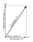
The relationship between impedance and its individual components (resistance and inductive reactance) can be represented using a vector as shown below. The amplitude of the resistance component is shown by a vector along the x-axis and the amplitude of the inductive reactance is shown by a vector along the y-axis. The amplitude of the the impedance is shown by a vector that stretches from zero to a point that represents both the resistance value in the x-direction and the inductive reactance in the y-direction. Eddy current instruments with impedance plane displays present information in this format.
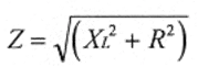
The impedance in a circuit with resistance and inductive reactance can be calculated using the following equation. If capacitive reactance was present in the circuit, its value would be added to the inductance term before squaring.
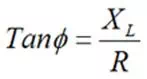
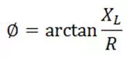
The phase angle of the circuit can also be calculated using some trigonometry. The phase angle is equal to the ratio between the inductance and the resistance in the circuit. With the probes and circuits used in nondestructive testing, capacitance can usually be ignored so only inductive reactance needs to be accounted for in the calculation. The phase angle can be calculated using the equation below. If capacitive reactance was present in the circuit, its value would simply be subtracted from the inductive reactance term.
|
|
or |
|
Impedance and Ohm's Law
In previous pages, Ohm's Law was discussed for a purely resistive circuit. When there is inductive reactance or capacitive reactance also present in the circuit, Ohm's Law must be written to include the total impedance in the circuit. Therefore, Ohm's law becomes:
I = V / Z
Ohm's law now simply states that the current (I), in amperes, is proportional to the voltage (V), in volts, divided by the impedance(Z), in ohms.
Also note that when there is inductance in the circuit, the voltage and current are out of phase. This is because the voltage across the inductor will be a maximum when the rate of change of the current is greatest. For a sinusoidal wave form like AC, this is at the point where the actual current is zero. Thus the voltage applied to an inductor reaches its maximum value a quarter-cycle before the current does, and the voltage is said to lead the current by 90o.