Circuits and Phase
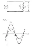
A circuit can be thought of as a closed path in which current flows through the components that make up the circuit. The current (i) obeys Ohm's Law, which is discussed on the page on current flow. The simple circuit below consists of a voltage source (in this case an alternating current voltage source) and a resistor. The graph below the circuit diagram shows the value of the voltage and the current for this circuit over a period of time. This graph shows one complete cycle of an alternating current source. From the graph, it can be seen that as the voltage increases, the current does the same. The voltage and the current are said to be "in-phase" since their zero, peak, and valley points occur at the same time. They are also directly proportional to each other.
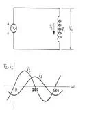
In the circuit below, the resistive component has been replaced with an inductor. When inductance is introduced into a circuit, the voltage and the current will be "out-of-phase," meaning that the voltage and current do not cross zero, or reach their peaks and valleys at the same time. When a circuit has an inductive component, the current (iL) will lag the voltage by one quarter of a cycle. One cycle is often referred to as 360o, so it can be said that the current lags the voltage by 90o.
This phase shift occurs because the inductive reactance changes with changing current. Recall that it is the changing magnetic field caused by a changing current that produces inductive reactance. When the change in current is greatest, inductive reactance will be the greatest, and the voltage across the inductor will be the highest. When the change in current is zero, the inductive reactance will be zero and the voltage across the inductor will be zero. Be careful not to confuse the amount of current with the amount of change in the current. Consider the points where the current reaches it peak amplitude and changes direction in the graph below (0o, 180o, and 360o). As the current is changing directions, there is a split second when the change in current is zero. Since the change in current is zero, no magnetic field is generated to produce the inductive reactance. When the inductive reactance is zero, the voltage across the inductor is zero.
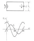
The resistive and inductive components are of primary interest in eddy current testing since the test probe is basically a coil of wire, which will have both resistance and inductive reactance. However, there is a small amount of capacitance in the circuits so a mention is appropriate. This simple circuit below consists of an alternating current voltage source and a capacitor. Capacitance in a circuit caused the current (ic) to lead the voltage by one quarter of a cycle (90o current lead).
When there is both resistance and inductive reactance (and/or capacitance) in a circuit, the combined opposition to current flow is known as impedance.