Self-Inductance and Inductive Reactance
The property of self-inductance is a particular form of electromagnetic induction. Self inductance is defined as the induction of a voltage in a current-carrying wire when the current in the wire itself is changing. In the case of self-inductance, the magnetic field created by a changing current in the circuit itself induces a voltage in the same circuit. Therefore, the voltage is self-induced.
The term inductor is used to describe a circuit element possessing the property of inductance and a coil of wire is a very common inductor. In circuit diagrams, a coil or wire is usually used to indicate an inductive component. Taking a closer look at a coil will help understand the reason that a voltage is induced in a wire carrying a changing current. The alternating current running through the coil creates a magnetic field in and around the coil that is increasing and decreasing as the current changes. The magnetic field forms concentric loops that surround the wire and join to form larger loops that surround the coil as shown in the image below. When the current increases in one loop the expanding magnetic field will cut across some or all of the neighboring loops of wire, inducing a voltage in these loops. This causes a voltage to be induced in the coil when the current is changing.
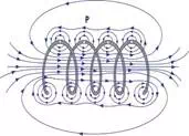
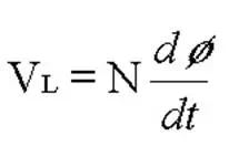
By studying this image of a coil, it can be seen that the number of turns in the coil will have an effect on the amount of voltage that is induced into the circuit. Increasing the number of turns or the rate of change of magnetic flux increases the amount of induced voltage. Therefore, Faraday's Law must be modified for a coil of wire and becomes the following.
Where:
VL = induced voltage in volts
N = number of turns in the coil
dø/dt = rate of change of magnetic flux in
webers/second
The equation simply states that the amount of induced voltage (VL) is proportional to the number of turns in the coil and the rate of change of the magnetic flux (dø/dt). In other words, when the frequency of the flux is increased or the number of turns in the coil is increased, the amount of induced voltage will also increase.
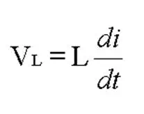
In a circuit, it is much easier to measure current than it is to measure magnetic flux, so the following equation can be used to determine the induced voltage if the inductance and frequency of the current are known. This equation can also be reorganized to allow the inductance to be calculated when the amount of inducted voltage can be determined and the current frequency is known.
Where:
VL = the induced voltage in volts
L = the value of inductance in henries
di/dt = the rate of change of current in amperes per second
Lenz's Law
Soon after Faraday proposed his law of induction, Heinrich Lenz developed a rule for determining the direction of the induced current in a loop. Basically, Lenz's law states that an induced current has a direction such that its magnetic field opposes the change in magnetic field that induced the current. This means that the current induced in a conductor will oppose the change in current that is causing the flux to change. Lenz's law is important in understanding the property of inductive reactance, which is one of the properties measured in eddy current testing.
Inductive Reactance
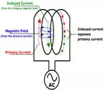
The reduction of current flow in a circuit due to induction is called inductive reactance. By taking a closer look at a coil of wire and applying Lenz's law, it can be seen how inductance reduces the flow of current in the circuit. In the image below, the direction of the primary current is shown in red, and the magnetic field generated by the current is shown in blue. The direction of the magnetic field can be determined by taking your right hand and pointing your thumb in the direction of the current. Your fingers will then point in the direction of the magnetic field. It can be seen that the magnetic field from one loop of the wire will cut across the other loops in the coil and this will induce current flow (shown in green) in the circuit. According to Lenz's law, the induced current must flow in the opposite direction of the primary current. The induced current working against the primary current results in a reduction of current flow in the circuit.
It should be noted that the inductive reactance will increase if the number of winds in the coil is increased since the magnetic field from one coil will have more coils to interact with.
Similarly to resistance, inductive reactance reduces the flow of current in a circuit. However, it is possible to distinguish between resistance and inductive reactance in a circuit by looking at the timing between the sine waves of the voltage and current of the alternating current. In an AC circuit that contains only resistive components, the voltage and the current will be in-phase, meaning that the peaks and valleys of their sine waves will occur at the same time. When there is inductive reactance present in the circuit, the phase of the current will be shifted so that its peaks and valleys do not occur at the same time as those of the voltage. This will be discussed in more detail in the section on circuits.