Equipment
|
|
|
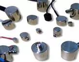
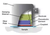
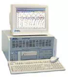
Acoustic emission testing can be performed in the field with portable instruments or in a stationary laboratory setting. Typically, systems contain a sensor, preamplifier, filter, and amplifier, along with measurement, display, and storage equipment (e.g. oscilloscopes, voltmeters, and personal computers). Acoustic emission sensors respond to dynamic motion that is caused by an AE event. This is achieved through transducers which convert mechanical movement into an electrical voltage signal. The transducer element in an AE sensor is almost always a piezoelectric crystal, which is commonly made from a ceramic such as leadzirconate titanate (PZT). Transducers are selected based on operating frequency, sensitivity and environmental characteristics, and are grouped into two classes: resonant and broadband. The majority of AE equipment is responsive to movement in its typical operating frequency range of 30 kHz to 1 MHz. For materials with high attenuation (e.g. plastic composites), lower frequencies may be used to better distinguish AE signals. The opposite holds true as well.
Ideally, the AE signal that reaches the mainframe will be free of background noise and electromagnetic interference. Unfortunately, this is not realistic. However, sensors and preamplifiers are designed to help eliminate unwanted signals. First, the preamplifier boosts the voltage to provide gain and cable drive capability. To minimize interference, a preamplifier is placed close to the transducer; in fact, many transducers today are equipped with integrated preamplifiers. Next, the signal is relayed to a bandpass filter for elimination of low frequencies (common to background noise) and high frequencies. Following completion of this process, the signal travels to the acoustic system mainframe and eventually to a computer or similar device for analysis and storage. Depending on noise conditions, further filtering or amplification at the mainframe may still be necessary.
|
Schematic Diagram of a Basic Four-channel Acoustic Emission Testing System |
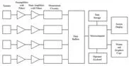
After passing the AE system mainframe, the signal comes to a detection/measurement circuit as shown in the figure directly above. Note that multiple-measurement circuits can be used in multiple sensor/channel systems for source location purposes (to be described later). At the measurement circuitry, the shape of the conditioned signal is compared with a threshold voltage value that has been programmed by the operator. Signals are either continuous (analogous to Gaussian, random noise with amplitudes varying according to the magnitude of the AE events) or burst-type. Each time the threshold voltage is exceeded, the measurement circuit releases a digital pulse. The first pulse is used to signify the beginning of a hit. (A hit is used to describe the AE event that is detected by a particular sensor. One AE event can cause a system with numerous channels to record multiple hits.) Pulses will continue to be generated while the signal exceeds the threshold voltage. Once this process has stopped for a predetermined amount of time, the hit is finished (as far as the circuitry is concerned). The data from the hit is then read into a microcomputer and the measurement circuit is reset.
Hit Driven AE Systems and Measurement of Signal Features
 Although several AE system designs are available (combining various
options, sensitivity, and cost), most AE systems use a hit-driven architecture.
The hit-driven design is able to efficiently measure all detected signals and
record digital descriptions for each individual feature (detailed later in this
section). During periods of inactivity, the system lies dormant. Once a new
signal is detected, the system records the hit or hits, and the data is logged
for present and/or future display.
Although several AE system designs are available (combining various
options, sensitivity, and cost), most AE systems use a hit-driven architecture.
The hit-driven design is able to efficiently measure all detected signals and
record digital descriptions for each individual feature (detailed later in this
section). During periods of inactivity, the system lies dormant. Once a new
signal is detected, the system records the hit or hits, and the data is logged
for present and/or future display.
Also common to most AE systems is the ability to perform routine tasks that are valuable for AE inspection. These tasks include quantitative signal measurements with corresponding time and/or load readings, discrimination between real and false signals (noise), and the collection of statistical information about the parameters of each signal.