|
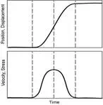
Primitive AE wave released at a source. The primitive wave is essentially a stress pulse corresponding to a permanent displacement of the material. The ordinate quantities refer to a point in the material.
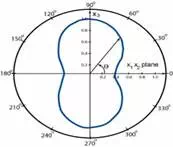
Angular dependence of acoustic emission radiated from a growingmicrocrack. Most of the energy is directed in the 90 and 270odirections, perpendicular to the crack surfaces. |
Theory - Acoustic Waves
Wave Propagation
A primitive wave released at the AE source is illustrated in the figure right. The displacement waveform is a step-like function corresponding to the permanent change associated with the source process. The analogous velocity and stress waveforms are essentially pulse-like. The width and height of the primitive pulse depend on the dynamics of the source process. Source processes such as microscopic crack jumps and precipitate fractures are usually completed in a fraction of a microsecond or a few microseconds, which explains why the pulse is short in duration. The amplitude and energy of the primitive pulse vary over an enormous range from submicroscopicdislocation movements to gross crack jumps.
Waves radiates from the source in all directions, often having a strong directionality depending on the nature of the source process, as shown in the second figure. Rapid movement is necessary if a sizeable amount of the elastic energy liberated during deformation is to appear as an acoustic emission.
As these primitive waves travel through a material, their form is changed considerably. Elastic wave source and elastic wave motion theories are being investigated to determine the complicated relationship between the AE source pulse and the corresponding movement at the detection site. The ultimate goal of studies of the interaction between elastic waves and material structure is to accurately develop a description of the source event from the output signal of a distant sensor.
However, most materials-oriented researchers and NDT inspectors are not concerned with the intricate knowledge of each source event. Instead, they are primarily interested in the broader, statistical aspects of AE. Because of this, they prefer to use narrow band (resonant) sensors which detect only a small portion of the broadband of frequencies emitted by an AE. These sensors are capable of measuring hundreds of signals each second, in contrast to the more expensive high-fidelity sensors used in source function analysis. More information on sensors will be discussed later in the Equipment section.
The signal that is detected by a sensor is a combination of many parts of the waveform initially emitted. Acoustic emission source motion is completed in a few millionths of a second. As the AE leaves the source, the waveform travels in a spherically spreading pattern and is reflected off the boundaries of the object. Signals that are in phase with each other as they reach the sensor produce constructive interference which usually results in the highest peak of the waveform being detected. The typical time interval from when an AE wave reflects around the test piece (repeatedly exciting the sensor) until it decays, ranges from the order of 100 microseconds in a highly damped, nonmetallic material to tens of milliseconds in a lightly damped metallic material.
Attenuation
The intensity of an AE signal detected by a sensor is considerably lower than the intensity that would have been observed in the close proximity of the source. This is due to attenuation. There are three main causes of attenuation, beginning with geometric spreading. As an AE spreads from its source in a plate-like material, its amplitude decays by 30% every time it doubles its distance from the source. In three-dimensional structures, the signal decays on the order of 50%. This can be traced back to the simple conservation of energy. Another cause of attenuation is material damping, as alluded to in the previous paragraph. While an AE wave passes through a material, its elastic and kinetic energies are absorbed and converted into heat. The third cause of attenuation is wave scattering. Geometric discontinuities (e.g. twin boundaries, nonmetallicinclusions, or grain boundaries) and structural boundaries both reflect some of the wave energy that was initially transmitted.
Measurements of the effects of attenuation on an AE signal can be performed with a simple apparatus known as a Hsu-Nielson Source. This consists of a mechanical pencil with either 0.3 or 0.5 mm 2H lead that is passed through a cone-shaped Teflon shoe designed to place the lead in contact with the surface of a material at a 30 degree angle. When the pencil lead is pressed and broken against the material, it creates a small, local deformation that is relieved in the form of a stress wave, similar to the type of AE signal produced by a crack. By using this method, simulated AE sources can be created at various sites on a structure to determine the optimal position for the placement of sensors and to ensure that all areas of interest are within the detection range of the sensor or sensors.
Wave Mode and Velocity
As mentioned earlier, using AE inspection in conjunction with other NDE techniques can be an effective method in gauging the location and nature of defects. Since source locations are determined by the time required for the wave to travel through the material to a sensor, it is important that the velocity of the propagating waves be accurately calculated. This is not an easy task since wave propagation depends on the material in question and the wave mode being detected. For many applications, Lamb waves are of primary concern because they are able to give the best indication of wave propagation from a source whose distance from the sensor is larger than the thickness of the material. For additional information on Lamb waves, see the wave mode page in the Ultrasonic Inspection section.