Calculating Screw Jacks
Screw Jacks are devices used for raising and lowering heavy objects (weights) through external small manual labor. The article discusses the various calculations involved and explains the relation between weight which is to be lifted and the applied external force associated with these devices.
Screw jacks are mechanical devices which are used to raise and lower heavy objects vertically through the application of a smaller external force in a circular path.
Screw jacks were especially developed with the aim of solving the issue of raising and lowering large and heavy objects over ground levels easily through relatively smaller magnitudes of external effort.
Using a screw jack thus makes it possible the lifting and lowering of huge objects like automobiles, heavy industrial machines, etc.
These devices find an important place and utility in automobile garages. Here heavy vehicles which require servicing from underneath are easily hoisted above the ground using a screw jack for the necessary inspections and troubleshooting.
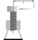
Basically screw jacks are mechanical devices consisting of a heavy bottom metallic base or stand through which a screw mechanism is allowed to slide up and down through a circular path over a central axis. The load that is to be lifted is place dover the top “head" of the screw mechanism. The lifting movement or operation is made functional by applying an external physical force (using human hands) through a radial motion.
A careful inspection of the screw movement (unwinding) through a single thread shows that the elevating movement follows the principle of an inclined plane.
Primarily two major factors are involved with the functioning of a screw jack, viz. the weight lifted and the effort applied.
Let’s try to understand and derive a relation between the above two parameters responsible for the operation of a screw jack.
Relating Effort and the Weight Lifted in Screw Jacks
Let’s assume a few of the elements associated with the above two parameters and assign them in the following manner:
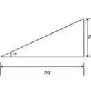
p = pitch of the screw,
d = mean diameter of the screw and,
α = helix angle.
Also a cross-sectional analysis of the produced angular displacement can be illustrated with the diagram shown alongside and the following expression:
tan α = P/πd
Now assume,
P = the effort applied for lifting the load,
W = Weight of the body being lifted and
µ = Coefficient of friction, between the screw threads and the stand threads.
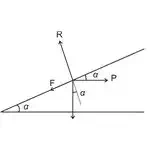
As discussed earlier, since the calculations involved with a screw jack is similar and can be compared to that of an inclined plane, we can consider the external applied force to be horizontal.
Also, the weight which is being elevated generates a friction F acting downwards equal to:
F = µR
Where F = force of friction,
µ = coefficient of friction,
And R = normal reaction developed between the interacting surfaces.
Resolving the forces over the horizontal plane gives:
P cos α = W sin α + µR
Similarly, resolving the perpendicular forces gives:
R = P sin α + W cos α
Substituting the value of R in equation ( i ), we get:
P cos α = W sin α + µR = W sin α + µ(P sin α + W cos α)
= W sin α + µP sin α + µW cos α
Or P cos α – µP sin α = W sin α + µW cos α
Or P(cos α – µ sin α) = W(sin α + µ cos α)
Or P = W × (sin α + µ cos α) / (cos α – µ sin α)
Replacing the value of µ = tan φ,
P = W × (sin α + tan φ cos α) / (cos α – tan φ sin α)
Multiplying the numerator and the denominator by a common factor cos φ, we get
P = W × (sin α + cos φ + sin φ cos α) / (cos α cos φ – sin α sin φ),
= W × sin (α + φ) / cos (α + φ),
Finally, we write,
P = W tan (α + φ)
The above expression presents a clear relation between the weight P which is to be raised and the effort W needed to be applied externally using screw jacks.