How to Calculate Leaf Springs
The effortless, easy and comfortable experience produced while traveling in vehicles may be largely due to the incorporation of these magnificent devices called leaf springs. However designing these engineering marvels or calculating leaf springs may involve many considerations and formulas.
● A spring is a multilayered arrangement made up of specially seasoned metals which exhibit outstanding resilient properties against all sorts of forced stresses and strains. These devices therefore find their major applications as shock absorbers mostly in vehicles, but actually you will find them being used everywhere, whether it’s a inside the ball pens, gas lighters, or the toys they have today become almost an indispensible part of our life.
● Although springs may be of many different kinds, the following two are most commonly used in the engineering field: Laminated or Leaf Spring and Helical Spring.
● Here we are discussing leaf springs and the various expressions used for calculating leaf springs.
● From the engineering point of view, designing a leaf spring can be critical, requiring many considerations in order to produce the most suitable design that is able to sustain the calculated loads and help absorb shocks optimally.
● Fundamentally, the parameters required for the calculations of leaf springs are:
○ Bending Moment,
○ Moment of Inertia,
○ Resisting Moment, and
○ Central Deflection
● Let's derive and learn each of the above expressions in a step-wise manner.
How to Measure Leaf Springs
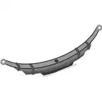
● A quick peek under any four wheeler automobile will provide you with an instant view of these important devices, or leaf springs, used extensively as suspensions for the sole purpose of absorbing possible shocks due to accidental bumps and rough roads. They are normally situated at the edges of the wheel axles.
● But how do you measure leaf springs that would guarantee an ideal and a safe journey with the vehicles?
● Before we move into the technical details let’s first try to understand their basic structure.
● Referring to the figure alongside we find that a leaf spring is basically comprised of a number of parallel attached metal strips of decrementing lengths, but having the same width and thickness. The strips are arranged in such a way that they are free to slide one over the other.
● Under no load conditions, the shape of the strips of a leaf spring may appear bent over a certain radius in the form of an arc. However in the presence of a load, the orientations of the strips tend to straighten up, generating a cushioning effect to the applied load. The arrangement of the integrated strips makes sure that the load is distributed uniformly throughout the length of the entire leaf spring.
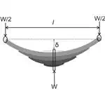
● In vehicles and railway carriages, leaf springs are normally fitted such that the wheel axle passes perpendicular and through the center of the spring while the two ends of the spring are pinned to the body or the chassis of the vehicle.
● Let’s assume the following parameters and denote them as follows:
● l = Length of the leaf spring,
● t = thickness of the strips,
● b = width of the strips,
● n = number of strips,
● W = load acting over the spring,
● f = ultimate bending stress produced over the strips,
● δ = original deflection of the topmost spring.
● A little analysis of the system shows that the load supported by the lowermost strip is shared equally by the ends of the top most strip.
● According to the standard formula. the Bending Moment (BM) developed at the center of the spring will be:
● M = Wl/4---------------------------------------( i )
● Similarly the Moment of inertia developed over the strips may be presented as:
● I = bt^2/12
● Also since the Resisting Moment M is expressed through the relation:
● M/I = f/y,
● Where M = resisting moment,
● I = Moment if Inertia,
● f = Bending Stress developed in the used material,
● y = distance of the above stress from the neutral axis.
● or M = f.I/y = f × bt^2/12 ÷ t/2 = f.bt^2/6
● Therefore the final expression indicating the Resisting Moment produced by n number of pates can be written as:
● M = nfbt^2/6 -------------------------------------( ii )
● Now since the Bending Moment and the Resisting Moments act in the opposite directions and are equal in magnitudes, equating the RHS of the respective expressions i.e. ( i ) and ( ii ) gives:
● Wl/4 = nfbt^2/6
● i.e. f = 3Wl/2nbt^2
● The above equation may be used for calculating the maximum stress developed across the plates of the spring.
● Now the shape of the leaf spring, or simply its geometry, indicates that the central deflection must be:
● δ = l^2/8R ------------------------------------------------------( iii )
● Also according to another standard formula,
● f/y = E/R
● where E = Young’s Modulus and R = Radius of curvature.
● Therefore R = E.y/f = Et/2f, (since y = t/2).
● Substituting the above value of R in equation ( iii ) gives:
● δ = l^2 ÷ 8 × E.t/2f
● or δ = fl^2/4Et.
● This final expression may be used to find out the central deflection while calculating leaf springs.