Difference between the Theoretical and Actual p-v diagram of a 4 stroke petrol Engine Actual suction
During the suction stroke the atmospheric air must be entered into
the engine cylinder. Then the suction pressure must be below the atmosphere
air. At the start of the suction stroke the piston speed is less, hence less
air will enter into the cylinder. Then the difference between the atmosphere
pressure and the suction pressure will be less at the start of the suction
stroke. Then the piston picks up the speed, where more air enters inside. The
pressure difference is considered to be higher. Finally the piston slows down
and come to rest at bottom dead center. Hence the pressure difference will
also be less. Actual suction process will be given by like 0 –![]() – 1
– 1
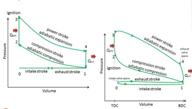
Actual compression:
Due to heat carried away by cold water, the actual compression
process is Polytropic. In account of heat loss the work input for the
actual compression process will be more. Hence area in the p-v diagram for
actual compression will be lesser. Hence the slop for the actual compression
process will be higher than the adiabatic index. Process is given by 1-c-![]()
Actual heat addition:
Heat addition takes place during the changing direction of the
piston at the top dead center. The volume first decreases and later
increases. Further, the pressure increases throughout heat addition. The
pressure increases through heat addition. The actual heat addition process is
given by ![]() – d –
– d –![]()
Actual Expression:
Due to heat carried away by cold water the work output from the
polytrophic expansion process is less. The expansion process is given by the
line is ![]() – e –
– e –![]()
Heat rejection:
The actual heat rejection is not a constant volume process. During
heat rejection the piston under goes change in direction at bottom
dead center. The volume initially increases and then decreases. The
pressure decreases throughout heat rejection. It is given by the
line ![]() – f –
– f – ![]() .
.
Actual Exhaust:
During exhaust the leftover exhaust gas is pushed out by the
upward motion of the piston depending on the piston speed, the actual exhaust
process is given by 1- ![]() – 0
– 0
The area formed by the combustion of the suction and exhaust process is known as pumping of engine loss.
The following area must be taken as negative
(0 – ![]() – 1-
– 1- ![]() –
– ![]() – 0). The area
available due to the other operation is treated as positive where the net area
is determined.
– 0). The area
available due to the other operation is treated as positive where the net area
is determined.
The ratio of net actual indicated work done to the ideal indicated work done is defined as diagram factor of engine.
df = IWD actual/ IWD ideal.