Modeling Rotordynamic Systems with Cross-Coupled Interactions in FEA
Many conventional materials and structures behave in a manner where the direction of response is more or less in the same direction as the applied load. For example, a spring will act only in the direction of the applied load, with all other directions unaffected.
A situation where this behavior is not observed and where cross-coupling has great influence on a system is in the case of stability in high speed rotating machines with hydrodynamic bearings. The fluid between the shaft and bearing builds up pressure in the oil film based on the operating conditions. This pressure, or fluid reaction force, results in two components of load in the plane of rotation. One component resists the direct loading (weight, force, etc. on the shaft) and the other contributes a component of load in the plane of rotation, but tangent to the direct loading. One may need to look to an FEA consultant such as CAE Associates to help in this situation.
To capture this phenomenon in a transient finite element analysis, an element capable of coupling these two in-plane directions together should be used (two orthogonal springs in plane will not capture this interaction). The element needs to be capable of reacting the direct force, Fx=Kxxδx, and also imposing the cross coupling tangential reaction force due to the displacement in the direct force direction, Fy=Kyxδx. In a dynamic analysis, both the stiffness and damping terms can be cross coupled; these terms are circled below.
The orbit of an axisymmetric spinning shaft with an imbalance will be circular when no cross terms are present and the stiffness is the same in the two in-plane directions. This is sometimes modeled with two orthogonal springs connecting the shaft to the bearing. When the cross terms are present, the shaft's orbit can become elliptical, as shown below. The black circle becomes the red ellipse when the circled cross terms are included in a dynamic analysis. An element with cross-coupling capability must be used to capture this elliptical response.

Since the shaft is spinning and orbiting, the tangential component of the cross-coupled force can become large enough to overcome the system damping. This causes additional energy to be added to the system during each revolution and can lead to unstable whirling of the shaft. This behavior is shown below by tracking the orbit in the plane of rotation of a point on a rotating shaft. The upper left image is the most unstable as the orbit grows the largest in the smallest number of rotations. In this case, the added tangential force in the direction of the shaft's motion rapidly adds energy to the system. Increasing the damping in the system reduces the dynamic energy and leads to stability. Moving through the images shows how increased damping leads to a stable (but not circular) orbiting system by reducing the net destabilizing tangential force.
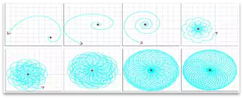
Aside from making fancy Spirograph images, these plots do show an unstable FEA system becoming stable. Many physical parameters in a hydrodynamic bearing control the stability and including these cross coupling terms makes it possible to predict the response of such a system.