Meshing Fabricated Structures in ANSYS Mechanical using Mesh Edit
The introduction of parallel part-by-part meshing to ANSYS Mechanical 15 back in 2013 was revolutionary. Structures which took hours to mesh now wrapped up in minutes, unfortunately removing one of our favourite excuses for taking a tactical nap. One of the limitations to this new feature was the fact that Multibody parts were still meshed in serial. Given that customers in the maritime, aviation and defence industries all utilised Multibody parts to connect shell assemblies, this was a pretty big drawback.

Introduced in R16 and refined in R17, ANSYS Inc have introduced a suite of tools focussed on “mesh editing” which work to enhance the workflow associated with meshing and connecting fabricated structures. Over the course of these two releases, a number of new features have been implemented:
● Improved shell meshing for better structured meshes

● Mesh edit tools for creating mesh connections post mesh generation
● Imprint tool in SpaceClaim to assist with the mesh connections approach to fabricated structures

● The ability to display element quality on geometry as a contour plot

● Weld Tool added to SCDM and DM to create weld bodies connecting adjacent surfaces

● Detach operation added to SCDM and DM which can be used to split large surface bodies into multiple surface bodies for an improved local control of the mesh

The addition of these features produces an entirely new workflow for fabricated structures, allowing node-node connectivity in fabricated shell structures while making use of parallel meshing. The overall procedure involved in this new workflow is:
1. Imprint mid-surface faces using Spaceclaim Direct Modeler.
2. Import geometry into Mechanical, delete any contact regions generated in locations intended for mesh connections.
3. Apply edge sizing to all imprinted edges (this step isn’t mandatory, however it will create cleaner connections in Mechanical) and then generate the mesh.
4. Merge adjacent nodes together using the Node Merge feature.
The following steps aim to demonstrate the implementation of the key points outlined above. We will be explaining the procedure using the bracket shown below:

Looking over the bracket, we can see that although the parts appear to be connected together, upon hiding the central stiffener, there are no imprinted edges where the intersection occurs with the parent material:

The Method
Imprinting Parts using SCDM
The first order of business is to imprint any edges which are in contact with adjacent faces, forcing the Mechanical mesher to place nodes on both sides of interface regions.
SpaceClaim makes this process simple;
1. Select the Prepare Tab.

2. Choose the Imprint button – this will detect any face/edge pairs which are within a user nominated tolerance and highlight them in red. Apply these changes.
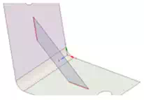
3. When hiding adjacent bodies you will now see the imprinted edges on parent faces (see bottom image). The geometry is now ready to be sent through to Mechanical for meshing.
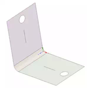
Importing Geometry into Mechanical
When the geometry is imported into Mechanical we can immediately see that the bodies comprising this assembly aren’t unified within a single Multibody part.
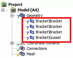
In this case no contact regions have been defined as the Edge-Face contact has been disabled as a default option. If Edge-Face contact regions are generated, suppress these contacts as our Mesh Connections will make them redundant.
Meshing
First of all we’ll need a reasonable quality mesh for the Mesh Connection feature. Although this step is optional we highly recommend it.
1. Select all edge pairs which we intend to merge using Mesh Connections.
2. Apply a sensible Edge Sizing to these edge pairs, ensuring the Behaviour is set to “Hard” – this will guarantee nodes will be in similar positions along the length of each edge.
3. Generate the mesh
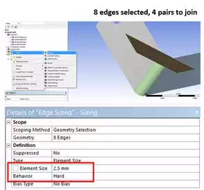
Observing the completed mesh, we can see that the Edge Sizing has forced nodes on either side of each edge pair to lie at similar positions along the length of the edge. At this stage these nodes, although coincident, are not connected together.

The Mesh Connections tools will merge nodes within a given user defined tolerance to complete the workflow.
Mesh Connections
1. Right click on Mesh branch of the tree > Insert > Node Merge Group
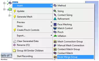
2. Choose a suitable tolerance value inside of which any nodes will be merged together. In our case we have chosen 0.1 mm as our edge sizing has ensured nodes are coincident. If the edge sizing step was skipped, a looser tolerance will be needed which could result in a poorer quality mesh. Care must be taken not to loosen the tolerance too far, as it may result in collapsed elements leading to solver issues.
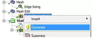
3. Right click on the Node Merge Group and click Generate
Once the Node Merge has completed, the Message window below the graphics window will report how many nodes were merged as a result of the operation:

We can see the effect of this operation on the mesh by inspecting the edge connectivity plot before and after the node merge was completed in the following image. A red edge corresponds to an edge connected to only one face, whereas the purple edge in the second image indicates a single edge connected to multiple faces.

This concludes the procedure explaining how to connect fabricated structures using the Node Merge feature within ANSYS Mechanical, allowing users to access the performance of parallel meshing while still retaining node-node connectivity.