Offshore Support Structures
Support structures for offshore wind turbines are highly dynamic, having to cope with combined wind and hydrodynamic loading and complex dynamic behaviour from the wind turbine. It is vital to capture the integrated effect of the wind and wave loads and the wind turbine control system, as this is a situation where the total loading is likely to be significantly less than the sum of the constituent loads. This is because the loads are not coincident, and because the aerodynamic damping provided by the rotor significantly damps the motions due to wave loading.
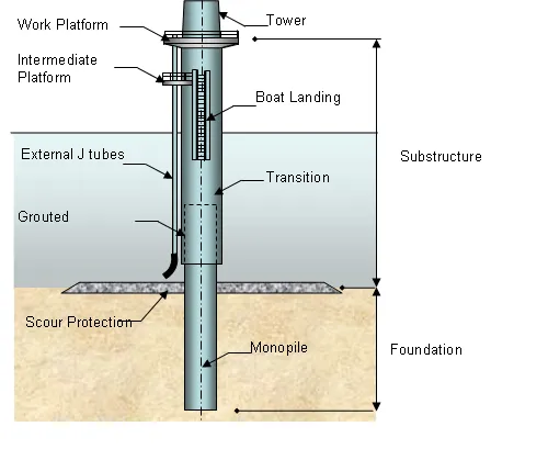
Structures to support wind turbines come in various shapes and sizes; the most common illustrated in Table 5.2 and Figures 5.6 to 5.9. Monopiles have been chosen for most of the installed offshore wind farms to date. Concrete gravity base structures have also been used on several projects. As wind turbines get larger, and are located in deeper water, jacket structures are expected to become more attractive.
The design process for offshore wind turbine support structures is illustrated in Figure 5.10.
Table 5.2: Support Structure Options
Structure | Examples | Use | Notes |
Monopile | Utgrunden (SE), Blyth (UK), Horns Rev (DK), North Hoyle (UK), Scroby Sands (UK), Arklow (IE) Ireland, Barrow (UK), Kentish Flats (UK), OWEZ (NL), Pricess Amalia (NL) | Shallow to medium water depths | · Made from steel tube, typically 4-6 m in diameter , |
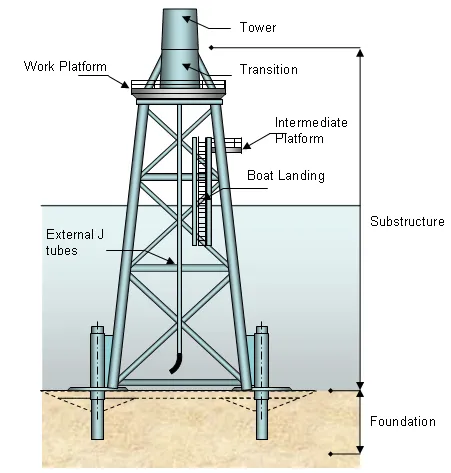
Jacket | Beatrice (UK), Alpha Ventus (DE) | Medium to deep water depths | · Made from steel tubes welded together, typically 0.5-1.5 m in diameter , |
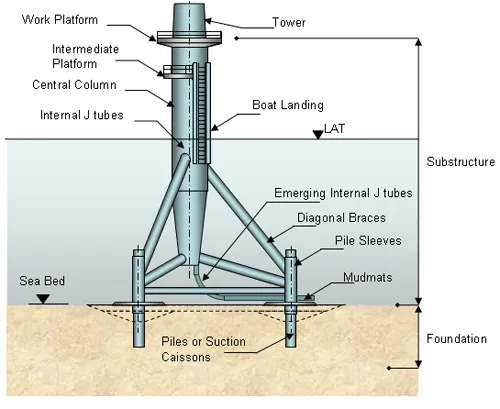
Tripod | Alpha Ventus (DE) | Medium to deep water depths | · Made from steel tubes welded together, typically 1.0-5.0 m in diameter , |
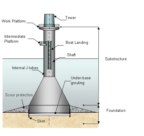
Gravity base | Vindeby (DK), Tuno Knob (DK), Middlegrunden (DK), Nysted (DK,) Lilgrund (SE), Thornton Bank (BE) | Shallow to medium water depths | · Made from steel or concrete, |
Floating structures | Karm øy (NO) | Deep to very deep water depths | · Still under development, |
Source: Garrad Hassan and Partners Ltd
Figure 5.7: Gravity Base Structure (Indicative Only: Actual Implementations Can Vary Significantly)
Source: Garrad Hassan and Partners Ltd
Figure 5.8: Jacket Structure
Source: Garrad Hassan and Partners Ltd
Figure 5.9: Tripod Structure (Third Leg Hidden)
Source: Garrad Hassan and Partners Ltd
Figure 5.10: Typical Primary Support Structure Design Inputs
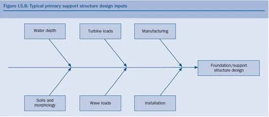
The structure designs are strongly influenced by metocean site conditions and site investigations. Metocean conditions are determined by detailed hydrodynamic analysis based on long-term hindcast model data and calibrated against short-term site wave measurements.
Site investigations are major tasks in their own right, requiring careful planning to achieve optimum results within programme and financial constraints. These involve a combination of geophysical and geotechnical measurements. The geotechnical investigations identify the physical properties of the soils into which foundations are to be placed and are achieved using cone penetrometer or borehole testing. Geophysical tests involve measurement of water depth and of the seismic properties of the underlying soil layers and can be used to interpolate the physical findings of geotechnical tests. The type and extent of geotechnical tests is dependent on the soil type occurring at the site and the homogeneity of those site conditions.
Design of the secondary structures, such as decks, boat landings and cable J-tubes is typically developed in the detailed design phase. These details have a major impact on ease of construction, support structure maintenance requirements, accessibility of the wind turbines and safety of personnel during the operations phase. Hence a significant design period is necessary.
Where an offshore substation is required, this is likely to require a substantial support structure, although as it does not have the complexities of wind turbine loading, it is a more conventional offshore structure to design. As discussed in the following section, an offshore substation may range from a unit of below 100 MW with a small single deck structure to a large, multi-tier HVDC platform.