Various Methods Used to Minimise Resistance on Ship’s Hull
When it comes to increasing ship’s efficiency, improving the hull efficiency is one of the most debated topic. Lately a lot of research has been put into developing ways to reduce the effects of friction on the ship’s hull.
Ships use large quantities of fuel to provide the necessary propulsive power to overcome resistance in their motion across ocean surfaces. In this article we shall be discussing about the various technologies/optimisation techniques used in the maritime industry to reduce the resistance on the hull of a ship.
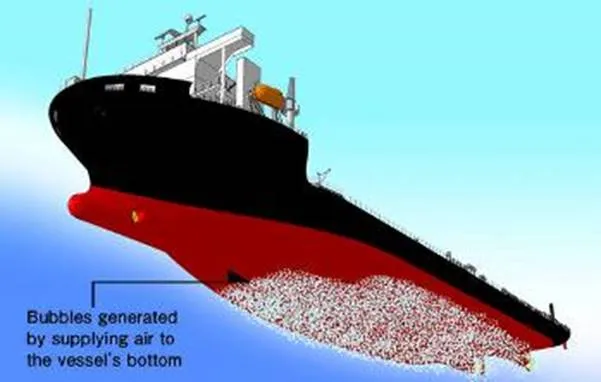
The air bubble distribution around the hull surface is believed to be an important parameter for reducing the resistance working on the hull, and must therefore be predicted accurately. In this method a layer of air bubbles is applied on the turbulent boundary layer developing downstream on the hull in the water flow. The efficiency of this method was determined by carrying out numerous model tests which proved that the effect of air lubrication helped reduce frictional resistance. The obtained results show that the maximum total resistance reduction was achieved up to 11% in ballast condition and about 6% in the full load condition with the assumption that thrust deduction is constant for with and without bubble injection. It was observed that the reduction rate of frictional resistance was larger on the bottom surface of the hull and its effect was smaller towards the sides of the ship.
During model tests it was found out that the effect of air bubbles in reducing frictional resistance persisted for the whole bottom area. This also helps in increasing the mean propeller inflow velocity with air lubrication from no air condition due to the viscous resistance reduction. Though much of this concept has been limited to theoretical and some practical tests, the efficiency of these tests suggest that the method can be adopted for large scale use for serving its actual purpose.
In fact, sea trials on MT Amalienborg (Tanker) which was fitted with the air lubrication system by Silverstream Technologies showed a net average efficiency savings of 4.3% and 3.8% for the vessel in ballast and laden conditions respectively. Based on these results the Norwegian Cruise line’s new build Norwegian Bliss would be fitted with the this technology.
Hull form optimisation has been recognised as a means to improve energy efficiency from decades. With numerous hull forms coming up, each one specialised in its own operation, several hull forms are available to choose from. When assessing hull form optimisation the owner has to consider the following options:
1. To accept the standard hull form design available at the shipyard who has taken your contract.
2. To modify an existing hull form design using line distortion method so as to achieve your desired profile.
3. To develop a new design by caring out various hydrostatic, hydrodynamic and structural analysis.
We shall not be discussing in depths about the various processes involved in the above three step, however, we will be focusing on the various procedures involved in minimising hull resistance and increasing the overall hull form efficiency. The following are the ways by which we can minimise hull resistance –
1. Fore body optimisation
2. Aft body optimisation
3. Appendage Resistance
Fore body optimisation includes development in the design of the forward region of the ship which includes consideration of the bulb design, forward shoulder, and waterline entrance. Potential flow calculation are routinely applied in this optimisation process.
The bulbous bow is designed in such a ways that it reduces the wave making resistance by producing its own wave, out of phase with the incoming wave system. This results in a destructive interference of the waves generated and the incoming waves, hence resulting in a cancelling effect. This was a significant amount of wave making resistance and be reduced thereby increasing the hull efficiency. The shape of the bulb also plays a significant role in doing the same.
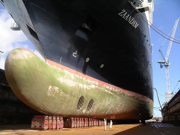
A V-shape may be introduced at the base of the bulb to mitigate slamming impact loads. Fuller ships such as tankers and bulk carriers are often arranged with bulbs having a large section area and V-shaped entrance, such that they behave as a traditional bulb at loaded draft and acts to extend the waterline length at ballast draft.
The biggest concerns while designing the aft part of the ship is to mitigate the stern waves, avoid eddies and improve the flow into the propeller. By improving the flow around the stern of the ship the hull resistance can be reduced. Flow improving devices such as stern flaps can be attached to do the same. The other important thing to be considered while designing the stern is the type of stern whether a transom or a cruiser or an elliptical etc. Each of them has its own set of pros and cons therefore, only after a proper CFD analysis or model experiments the appropriate stern has to be chosen
Hull form optimisation has been recognised as a means to improve energy efficiency from decades. With numerous hull forms coming up, each one specialised in its own operation, several hull forms are available to choose from. When assessing hull form optimisation the owner has to consider the following options:
1. To accept the standard hull form design available at the shipyard who has taken your contract.
2. To modify an existing hull form design using line distortion method so as to achieve your desired profile.
3. To develop a new design by caring out various hydrostatic, hydrodynamic and structural analysis.
We shall not be discussing in depths about the various processes involved in the above three step, however, we will be focusing on the various procedures involved in minimising hull resistance and increasing the overall hull form efficiency. The following are the ways by which we can minimise hull resistance –
1. Fore body optimisation
2. Aft body optimisation
3. Appendage Resistance
Fore body optimisation includes development in the design of the forward region of the ship which includes consideration of the bulb design, forward shoulder, and waterline entrance. Potential flow calculation are routinely applied in this optimisation process.
The bulbous bow is designed in such a ways that it reduces the wave making resistance by producing its own wave, out of phase with the incoming wave system. This results in a destructive interference of the waves generated and the incoming waves, hence resulting in a cancelling effect. This was a significant amount of wave making resistance and be reduced thereby increasing the hull efficiency. The shape of the bulb also plays a significant role in doing the same.

A V-shape may be introduced at the base of the bulb to mitigate slamming impact loads. Fuller ships such as tankers and bulk carriers are often arranged with bulbs having a large section area and V-shaped entrance, such that they behave as a traditional bulb at loaded draft and acts to extend the waterline length at ballast draft.

The biggest concerns while designing the aft part of the ship is to mitigate the stern waves, avoid eddies and improve the flow into the propeller. By improving the flow around the stern of the ship the hull resistance can be reduced. Flow improving devices such as stern flaps can be attached to do the same. The other important thing to be considered while designing the stern is the type of stern whether a transom or a cruiser or an elliptical etc. Each of them has its own set of pros and cons therefore, only after a proper CFD analysis or model experiments the appropriate stern has to be chosen.