Pressure relief valves
The pressure relief valves are used to protect the hydraulic components from excessive pressure. This is one of the most important components of a hydraulic system and is essentially required for safe operation of the system. Its primary function is to limit the system pressure within a specified range. It is normally a closed type and it opens when the pressure exceeds a specified maximum value by diverting pump flow back to the tank. The simplest type valve contains a poppet held in a seat against the spring force as shown in Figure 5.6.1. The fluid enters from the opposite side of the poppet. When the system pressure exceeds the preset value, the poppet lifts and the fluid is escaped through the orifice to the storage tank directly. It reduces the system pressure and as the pressure reduces to the set limit again the valve closes. This valve does not provide a flat cut-off pressure limit with flow rate because the spring must be deflected more when the flow rate is higher. Various types of pressure control valves are discussed in the following sections:
1. Direct type of relief valve
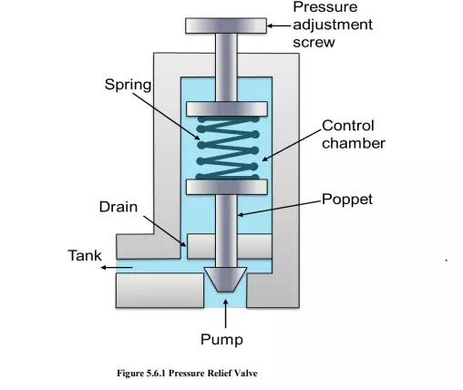
Schematic of direct pressure relief valve is shown in figure 5.6.1. This type of valves has two ports; one of which is connected to the pump and another is connected to the tank. It consists of a spring chamber where poppet is placed with a spring force. Generally, the spring is adjustable to set the maximum pressure limit of the system. The poppet is held in position by combined effect of spring force and dead weight of spool. As the pressure exceeds this combined force, the poppet raises and excess fluid bypassed to the reservoir (tank). The poppet again reseats as the pressure drops below the pre-set value. A drain is also provided in the control chamber. It sends the fluid collected due to small leakage to the tank and thereby prevents the failure of the valve.
2. Unloading Valve
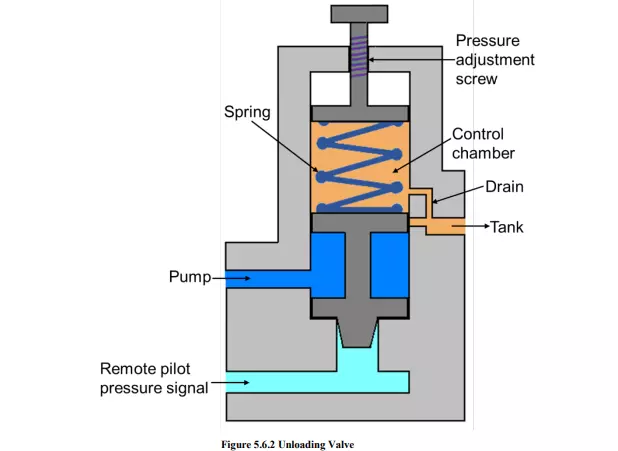
The construction of unloading valve is shown in Figure 5.6.2. This valve consists of a control chamber with an adjustable spring which pushes the spool down. The valve has two ports: one is connected to the tank and another is connected to the pump. The valve is operated by movement of the spool. Normally, the valve is closed and the tank port is also closed. These valves are used to permit a pump to operate at the minimum load. It works on the same principle as direct control valve that the pump delivery is diverted to the tank when sufficient pilot pressure is applied to move the spool. The pilot pressure maintains a static pressure to hold the valve opened. The pilot pressure holds the valve until the pump delivery is needed in the system. As the pressure is needed in the hydraulic circuit; the pilot pressure is relaxed and the spool moves down due to the selfweight and the spring force. Now, the flow is diverted to the hydraulic circuit. The drain is provided to remove the leaked oil collected in the control chamber to prevent the valve failure. The unloading valve reduces the heat buildup due to fluid discharge at a preset pressure value.
3. Sequence valve
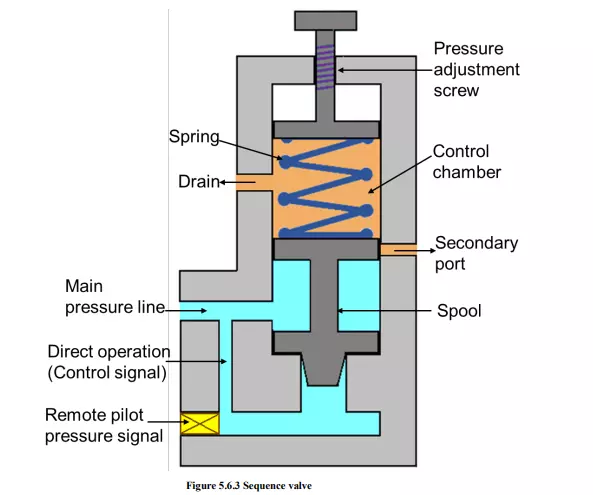
The primary function of this type of valve is to divert flow in a predetermined sequence. It is used to operate the cycle of a machine automatically. A sequence valve may be of direct-pilot or remote-pilot operated type.
Schematic of the sequence valve is shown in Figure 5.6.3. Its construction is similar to the direct relief valve. It consists of the two ports; one main port connecting the main pressure line and another port (secondary port) is connected to the secondary circuit. The secondary port is usually closed by the spool. The pressure on the spool works against the spring force. When the pressure exceeds the preset value of the spring; the spool lifts and the fluid flows from the primary port to the secondary port. For remote operation; the passage used for the direct operation is closed and a separate pressure source for the spool operation is provided in the remote operation mode.
4. Counterbalance Valve
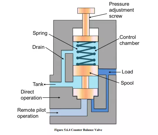
The schematic of counterbalance valve is shown in Figure 5.6.4. It is used to maintain the back pressure and to prevent a load from failing. The counterbalance valves can be used as breaking valves for decelerating heavy loads. These valves are used in vertical presses, lift trucks, loaders and other machine tools where position or hold suspended loads are important. Counterbalance valves work on the principle that the fluid is trapped under pressure until pilot pressure overcomes the pre-set value of spring force. Fluid is then allowed to escape, letting the load to descend under control. This valve is normally closed until it is acted upon by a remote pilot pressure source. Therefore, a lower spring force is sufficient. It leads to the valve operation at the lower pilot pressure and hence the power consumption reduces, pump life increases and the fluid temperature decreases.