Flow Control Valves
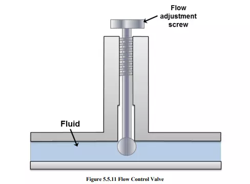
In practice, the speed of actuator is very important in terms of the desired output and needs to be controlled. The speed of actuator can be controlled by regulating the fluid flow. A flow control valve can regulate the flow or pressure of the fluid. The fluid flow is controlled by varying area of the valve opening through which fluid passes. The fluid flow can be decreased by reducing the area of the valve opening and it can be increased by increasing the area of the valve opening. A very common example to the fluid flow control valve is the household tap. Figure 5.5.11 shows the schematic diagram of a flow control valve. The pressure adjustment screw varies the fluid flow area in the pipe to control the discharge rate.
The pressure drop across the valve may keep on fluctuating. In general, the hydraulic systems have a pressure compensating pump. The inlet pressure remains almost constant but the outlet pressure keeps on fluctuating depending on the external load. It creates fluctuating pressure drop. Thus, the ordinary flow control valve will not be able to maintain a constant fluid flow. A pressure compensated flow control valve maintains the constant flow throughout the movement of a spool, which shifts its position depending on the pressure. Flow control valves can also be affected by temperature changes. It is because the viscosity of the fluid changes with temperature. Therefore, the advanced flow control valves often have the temperature compensation. The temperature compensation is achieved by the thermal expansion of a rod, which compensates for the increased coefficient of discharge due to decreasing viscosity with temperature.
Types of Flow Control Valves
The flow control valves work on applying a variable restriction in the flow path. Based on the construction; there are mainly four types viz. plug valve, butterfly valve, ball valve and balanced valve.
Plug or glove valve
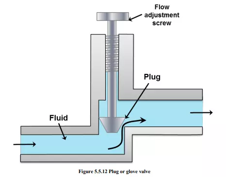
The plug valve is quite commonly used valve. It is also termed as glove valve. Schematic of plug or glove valve is shown in Figure 5.5.12. This valve has a plug which can be adjusted in vertical direction by setting flow adjustment screw. The adjustment of plug alters the orifice size between plug and valve seat. Thus the adjustment of plug controls the fluid flow in the pipeline. The characteristics of these valves can be accurately predetermined by machining the taper of the plug. The typical example of plug valve is stopcock that is used in laboratory glassware. The valve body is made of glass or teflon. The plug can be made of plastic or glass. Special glass stopcocks are made for vacuum applications. Stopcock grease is used in high vacuum applications to make the stopcock air-tight.
Butterfly valve
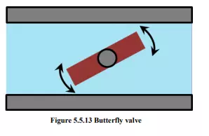
A butterfly valve is shown in Figure 5.5.13. It consists of a disc which can rotate inside the pipe. The angle of disc determines the restriction. Butterfly valve can be made to any size and is widely used to control the flow of gas. These valves have many types which have for different pressure ranges and applications. The resilient butterfly valve uses the flexibility of rubber and has the lowest pressure rating. The high performance butterfly valves have a slight offset in the way the disc is positioned. It increases its sealing ability and decreases the wear. For high-pressure systems, the triple offset butterfly valve is suitable which makes use of a metal seat and is therefore able to withstand high pressure. It has higher risk of leakage on the shut-off position and suffer from the dynamic torque effect. Butterfly valves are favored because of their lower cost and lighter weight. The disc is always present in the flow therefore a pressure drop is induced regardless of the valve position.
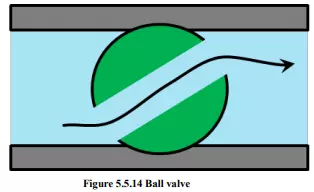
Ball Valve
The ball valve is shown in Figure 5.5.14. This type of flow control valve uses a ball rotated inside a machined seat. The ball has a through hole as shown in Figure 5.5.14. It has very less leakage in its shut-off condition. These valves are durable and usually work perfectly for many years. They are excellent choice for shutoff applications. They do not offer fine control which may be necessary in throttling applications. These valves are widely used in industries because of their versatility, high supporting pressures (up to 1000 bar) and temperatures (up to 250°C). They are easy to repair and operate.
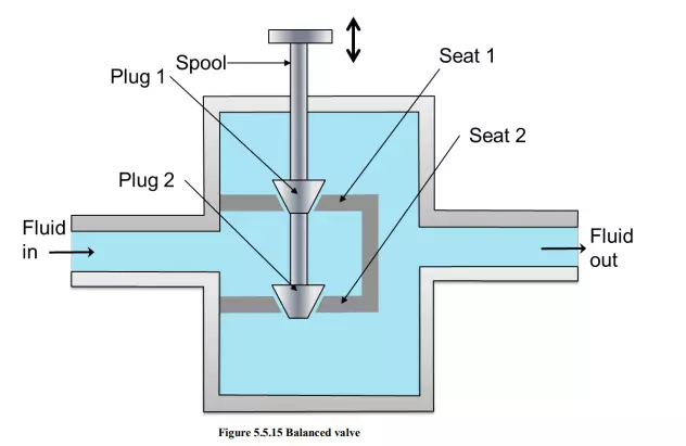
Balanced valve
Schematic of a balanced valve is shown in figure 5.5.15. It comprises of two plugs and two seats. The opposite flow gives little dynamic reaction onto the actuator shaft. It results in the negligible dynamic torque effect. However, the leakage is more in these kind of valves because the manufacturing tolerance can cause one plug to seat before the other. The pressure-balanced valves are used in the houses. They provide water at nearly constant temperature to a shower or bathtub despite of pressure fluctuations in either the hot or cold supply lines.