Control Valves -1
In a hydraulic system, the hydraulic energy available from a pump is converted into motion and force by means of an actuator. The control of these mechanical outputs (motion and force) is one of the most important functions in a hydraulic system. The proper selection of control selection ensures the desired output and safe function of the system. In order to control the hydraulic outputs, different types of control valves are required. It is important to know various types of control valves and their functions. This not only helps to design a proper hydraulic system but also helps to discover the innovative ways to improve the existing systems. In this lecture and next few lectures, various types of valves will be discussed.
There are basically three types of valves employed in hydraulic systems:
1. Directional control valves
2. Flow control valves
3. Pressure control valves
1. Direction control valve
Directional control valves are used to control the distribution of energy in a fluid power system. They provide the direction to the fluid and allow the flow in a particular direction. These valves are used to control the start, stop and change in direction of the fluid flow. These valves regulate the flow direction in the hydraulic circuit. These control valves contain ports that are external openings for the fluid to enter and leave. The number of ports is usually identified by the term ‘way’. For example, a valve with four ports is named as four-way valve. The fluid flow rate is responsible for the speed of actuator (motion of the output) and should controlled in a hydraulic system. This operation can be performed by using flow control valves. The pressure may increase gradually when the system is under operation. The pressure control valves protect the system by maintaining the system pressure within the desired range. Also, the output force is directly proportional to the pressure and hence, the pressure control valves ensure the desired force output at the actuator.
Directional control valves can be classified in the following manner:
1. Type of construction:
· Poppet valves
· Spool valve
2. Number of ports:
· Two- way valves
· Three – way valves
· Four- way valves.
3. Number of switching position:
· Two – position
· Three - position
4. Actuating mechanism:
· Manual actuation
· Mechanical actuation
· Solenoid actuation
· Hydraulic actuation
· Pneumatic actuation
· Indirect actuation
Type of construction
Check Valves
These are unidirectional valves and permit the free flow in one direction only. These valves have two ports: one for the entry of fluid and the other for the discharge. They are consists of a housing bore in which ball or poppet is held by a small spring force. The valve having ball as a closing member is known as ball check valve. The various types of check valves are available for a range of applications. These valves are generally small sized, simple in construction and inexpensive. Generally, the check valves are automatically operated. Human intervention or any external control system is not required. These valves can wear out or can generate the cracks after prolonged usage and therefore they are mostly made of plastics for easy repair and replacements.
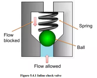
An important concept in check valves is the cracking pressure. The check valve is designed for a specific cracking pressure which is the minimum upstream pressure at which the valve operates. The simplest check valve is an inline check valve as shown in Figure 5.4.1. The ball is held against the valve seat by a spring force. It can be observed from the figure that the fluid flow is not possible from the spring side but the fluid from opposite side can pass by lifting the ball against. However, there is some pressure drop across the valve due to restriction by the spring force. Therefore these valves are not suitable for the application of high flow rate. When the operating pressure increases the valve becomes more tightly seated in this design.
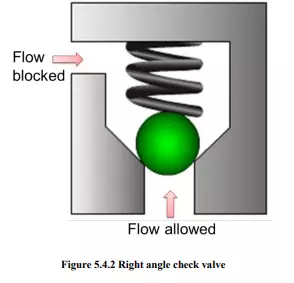
The advantages of the poppet valves include no leakage, long life and suitability with high pressure applications. These valves are commonly used in liquid or gel mini-pump dispenser spigots, spray devices, some rubber bulbs for pumping air, manual air pumps, and refillable dispensing syringes. Sometimes, the right angle check valve as shown in Figure 5.4.2 is used for the high flow rate applications. The pressure drop is comparatively less in right angle check valve.
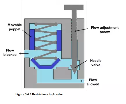
When the closing member is not a ball but a poppet energized by a spring is known as poppet valve. The typical poppet valve is shown in Figure 5.4.3. Some valves are meant for an application where free flow is required in one direction and restricted flow required in another direction. These types of valves are called as restriction check valve (see Figure 5.4.3). These valves are used when a direction sensitive flow rate is required. For example, the different actuator speeds are required in both the directions. The flow adjustment screw can be used to set the discharge (flow rate) in the restricted direction.
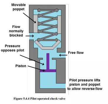
Another important type of check valve known as pilot operated check valve which is shown in figure 5.4.4. The function of the pilot operated check valve is similar to a normal check valve unless it gets an extra pressure signal through a pilot line. Pilot allows free flow in one direction and prevents the flow in another direction until the pilot pressure is applied. But when pilot pressure acts, the poppet opens and the flow is blocked from both the sides. These valves are used to stop the fluid suddenly.