Case Study 2
Problem Definition: Furnace door control
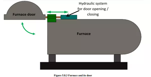
Design a hydraulic circuit for a furnace door to be opened and closed. Figure 5.8.3 shows the schematic of the furnace and its door that to be controlled. Propose a suitable hydraulic technology. List the components. Draw the hydraulic circuit diagram. Compute stroke speeds and stroke times by assuming assume suitable data.
Solution
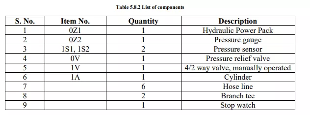
A double-acting cylinder can be used to control the movements of furnace door. The cylinder is to be activated by a 4/2-way valve with spring return. This will ensure that the door opens only as long as the valve is actuated. When the valve actuating lever is released, the door closes again. Table 5.8.2 lists the required hydraulic and mechanical components. Figure 5.8.4 shows the proposed hydraulic circuit.
Calculations
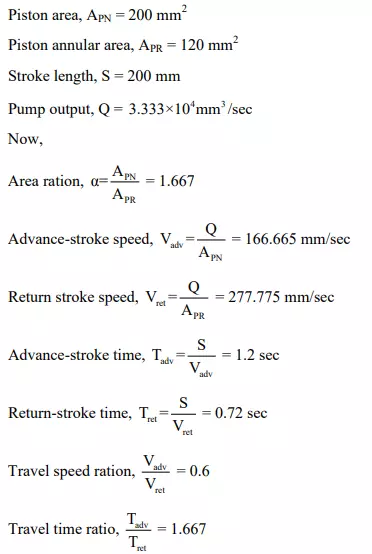
Let us assume the following data that required for the calculations:
Proposed hydraulic circuit and its operation
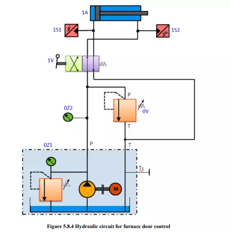
Figure 5.8.4 shows the hydraulic circuit for furnace door control. Once the circuit has been assembled and checked, the hydraulic power pack should be switched on and the system pressure set on the pressure relief valve 0V to a pre-set value. By operating the hand lever of valve 1V the opening and closing of the furnace can easily be carried out. When this 4/2-way valve is actuated, the piston rod of the cylinder will advance until the lever is released or the piston rod runs against the stop. When the lever is released, the piston rod will immediately return to its retracted end position. The hand lever can also be remotely operated by using suitable mechanism. Pressure sensors should be used to measure the travel and back pressures.