Gearing and tail shafts
Ships with low speed engines typically use direct drive from the crankshaft to the tail shaft with its propeller. Smaller domestic commercial vessels typically operate with high speed engines where direct drive shafts would revolve too fast to drag water across their propellers without efficiency losses due to cavitation (bubbling in the water flow). Consequently a gearbox is used to provide reduced speed of the shaft, reverse propulsion and through a clutch mechanism, disengaged propulsion.
Gears and clutch mechanisms
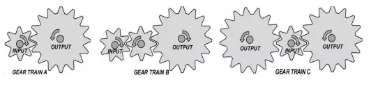
Principles of marine gear boxes Gearing is used in drive trains (sets of intermeshed gear wheels) to alter direction, position or speed/mechanical advantage of propulsion and auxiliary equipment such as winches, pumps and steering. The gear and shaft driven directly by the motor can be called the input and the final gear and shaft it drives can be called the output. Drive train A shown below illustrates reduction and reversal of the output, drive train B illustrates reduction only with further displacement (to the right) of the output, drive train C illustrates reduction and splitting into two outputs.
The efficient crankshaft speed of a small high speed motor is greater than the efficient speed of a propeller that revolves in relatively dense salt water. The solution to this is to use of a drive train with an input shaft and drive gear wheel enmeshed with a set of follower gear wheels connected to an output shaft (a gear box). The output shaft follower (to the propeller) has more gear teeth than the input shaft driver (from the crankshaft), and therefore it rotates more slowly. The number of teeth in each gear wheel has a direct relationship to not only the speed of the follower but also the transfer of torque. The reduction ratios shown in the drawings above are calculated by the:
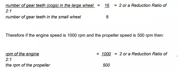
While the speed has been halved, the mechanical advantage has been doubled (not allowing for efficiency losses due to friction and heat). Marine gear boxes are designed to reduce the speed of the propeller shaft but some applications require a greater speed from the output shaft. This is simply achieved by using a smaller follower to give higher output speed with less mechanical advantage. It must also be noted that by adding a following gear wheel it will turn in the opposite direction to its driving wheel (in reverse).
Gear selection and engagement
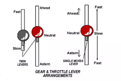
Gear box arrangements to select reverse gear include mechanically (using a gear lever directly or through a cable or linkage), electro-mechanically (using electrical solenoids which change the gears directly or hydraulically through clutches) or by hydraulic operation alone. The gearbox control and engine throttle (speed) may use separate levers for thrust and speed, or be combined in a single control lever as drawn below.
Marine transmission systems are heavy and generate considerable momentum so changing gear is smoothed by clutches. To avoid clashing of gears and overload on clutches the sequence of changing requires a delay for the propeller and shaft to slow down. Modern systems operate sequentially, or have override safety systems, however good practice remains to follow the manufacturer’s instructions always.
Clutches
In most operations it is convenient to be able to positively engage and disengage an input shaft from an output shaft. The mechanism that smooths this operation is called a clutch.
Basic clutch mechanisms
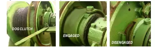
Dog clutch – The simplest arrangement as found on windlasses and winches is the dog clutch. Shown below, a collar is splined to the driving motors shaft that can be pushed by the clutch lever to engage hard against a lug in the winch drum’s side. This arrangement only allows engagement when winch and motor are stopped or both moving slowly at the same speed (a neat trick if at all possible for the arrangement shown below).
Dog clutches are not used in propulsion engines.
Cone clutch - The cone clutch does allow for engagement while the motor is running and is suitable for slow running operations such as capstans, windlasses and winches.
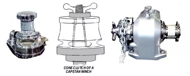
The warping drum (rope carrier) or gypsy (chain carrier) is machined with a tapered central hole. The drum is fitted over a matching tapered axle and can revolve smoothly when in the disengaged mode. The tapered axle can also be turned by a directly fitted motor. When the drum is tightened down onto the axle it grips (engages) and will turn with the motor driven axle. The system can snatch as it engages and although usually of heavy duty build, as with all friction type clutches there will always be momentary slip before engagement resulting in heat and wear.
More sophisticated systems are held in engagement with a heavy coil spring that can be manually compressed to disengage the drum from the axle. For a better grip the driving axle may be machined to mate inside a wide tapered drum and the mating cone’s surface be coated with a friction lining material. Cone clutches are rarely used in propulsion engines.
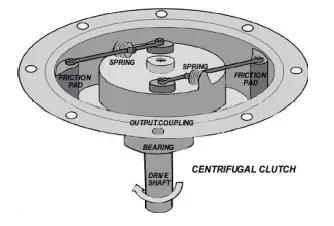
Centrifugal clutch - A driving shaft and output coupling drum can revolve independently at their common bearing. The driving shaft has hinged weighted friction pads that at rest are restrained clear of the drum’s surface by springs. When the driving shaft is revolved the friction pads are thrown outwards by centrifugal force sufficient to overcome the springs and bind onto the drums surface (engaging the coupling). Light duty pumps, power tools and the smallest outboards often use a centrifugal clutch for its light weight and economy.
Double de-clutching - Before the modern synchromesh gearbox the earliest motor cars used a crash gearbox. To change gear, a lever is first applied to rip the currently engaged gearwheel away from the output gear train and into neutral (disengaging the engine from the road wheels). While temporarily in neutral the accelerator is revved to boost the engine speed to match the speed of the lower gear wheel (determined by the road wheel speed). This is called double de-clutching. When the driver judges that the speeds are matched the gear lever is applied to enmesh the lower gear by crashing it into the engine gear wheel, with hopefully not too much crunching of the gear teeth. Such foot and hand control is not available in marine gearboxes so some means of smoothing the change of gears is required.