Air supply
Turbo charging
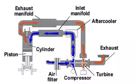
A turbo charger (sometimes called a turbo blower) can be fitted to both two and four stroke engines to increase the volumetric efficiency and thus their power output. It uses the force of the expelled exhaust gasses passing through a turbine to drive a rotor blowing air into the air inlet.
Advantages - The advantage of a turbo charger is that fuel consumption is lower than that of a normally aspirated engine of the same power output. In addition, the turbo charger utilises the exhaust gases of the engine so no additional power from the engine is required to drive it.
The turbo charger inducts a larger mass of air into the cylinder to that of a same cubic capacity normally aspirated engine. This allows for a proportional increase in the amount of fuel that can be injected and burnt in the cylinder thereby providing an increase in the power output of the engine.
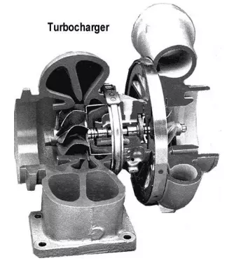
Components of a turbocharger
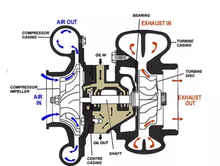
A cut away of a turbocharger’s components are shown below:
Rotor assembly - It has a rotor shaft which has exhaust gas turbine blades on one end and air compressor blades on the other end.
Casings - The exhaust gas turbine blades are housed in a casing which is attached to the exhaust manifold and to the exhaust pipe. Some casings are fresh water cooled to minimise the heat radiated out into the engine space. This allows for a cooler engine space, cooler air entering the engine air intake and therefore more power again. A nozzle ring is fitted inside the casing to direct the flow of exhaust gases to the turbine blades.
The air compressor blades are also housed in a casing which has an air cleaner on the intake side and is connected to the intake manifold on the discharge side. Where an engine is after cooled, the discharge side is connected to the after cooler which is then connected to the intake manifold. Both the above casings are attached to a centre casing which contains the bearings, seals and method of lubrication.
Bearings and lubrication - The shaft may rotate in white metal bearings which can be lubricated from the engine driven oil pump. This method of lubrication also allows the oil to remove some of the heat in the turbo charger. One bearing locates the shaft and takes the small residual thrust, the other bearing allows the shaft to move longitudinally to accommodate the differential thermal expansion of casings and shafting.
Alternatively, the smaller turbo chargers usually incorporate a ball bearing for positioning at the compressor end and a roller bearing to accommodate axial expansion at the turbine end of the rotor shaft. The bearings may have their own reservoir which forms part of the turbo charger. These reservoirs usually have round oil level sight glasses with two horizontal lines marked to indicate the high and low levels. Seals are fitted to retain the oil.