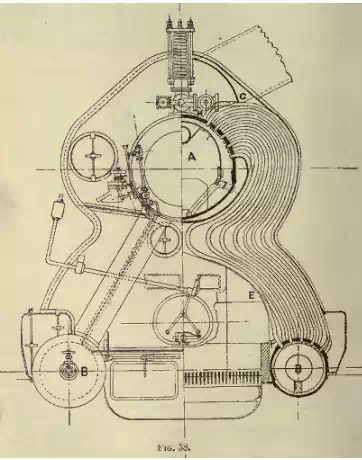
The Thornycroft boiler
The Thornycroft boiler ('Speedy' type) Fig. 58, consists
essentially of a central upper steam cylinder A, and two smaller lower water
cylinders B, these latter being fitted about the level of the fire-bars.
Figure 58 A series of steam generating tubes of small diameter are fitted
between the upper cylinder and each of the lower water cylinders. They are
secured at each end by being simply rolled into the cylinder plating by means
of the roller expander, the parts of the cylinders into which they are rolled
being made thick enough for this purpose. These tubes form practically the
whole of the heating surface of the boiler, and the inner row on each side is
curved in such a manner that they are close together at the top and form the
roof of the furnace or combustion chamber. ........
Thornycroft (Daring) type.
The length of the 'Speedy's' boilers to allow for return tubes is considerable,
the tubes are not very accesslble, and the height of the furnace is not
great, so that when the demand for torpedo-boat destroyers came, in order to
meet their special requirements as regards lightness, also to give an improved
furnace and greater means of access to the tubes, a modified type of boiler was
designed, known as the Thornycroft (Daring) type (Figs. 59 and 60). This type
obtains two furnaces' in each boiler and a greater amount of fire-grate in the
available space.
It consists of an upper cylinder A similar to
that of the preceding type, into which the upper ends of the generating tubes
are rolled.
Vertically below this is the principal lower cylinder B, to which the lower
ends of the majority of the tubes are attached.
Two smaller water cylinders, D, are arranged on each side of the principal
lower cylinder, and the furnaces are situated between them.
Three rows of generating tubes connect the upper cylinder to each of the small
water cylinders D and form the outside boundaries of the furnaces, the inner
boundaries being made by the tubes connecting the upper cylinder A with the
principal lower one.

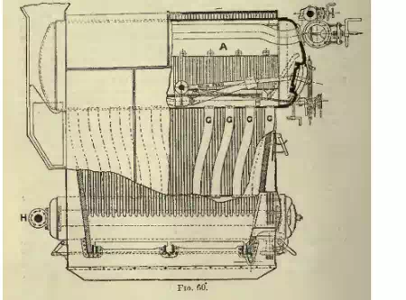
Of the three
rows connected to the small water cylinder, the outside two touch each other,
and so form a water wall which confines the flames and gases. The main body of
the tubes are so curved as to leave a considerable space, C, between the two
groups on each side; the gases are discharged into this space, which forms the
uptake of the boiler.
The inner and outer rows of tubes of each centre group are formed as walls of
tubes, except at the lower part of the furnace side and upper part of the
uptake side, where spaces are left for the entry and exit of gases.
The gases, after leaving the fire, enter through the spaces E, at the bottom of
the outer row, pass up between the walls among the tubes, and emerge
through the spaces F at the top of the inner rows to the uptake space C,
between the two centre groups of tubes. They proceed along this space to the
end of the boiler and thence to the funnel. ..........