Arrangement And Efficiency Of Boilers - Water Tank Boilers.
Low-pressure boilers.
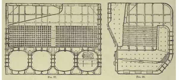
The first boilers fitted to work marine engines were of the rectangular, or
'box' form; an example of this type is shown in Figs. 27 and 28, which represent
the most general type of marine boiler for steam pressures not exceeding
from 30 to 40 lbs. per square inch above the atmosphere.
This form is now entirely obsolete for new
vessels, not being suitable for high pressures, as in these boilers the
stresses are resisted principally by the action of straight iron stay-rods. For
pressures above 30 or 40 lbs. per square inch, these would have to be so
numerous and closely spaced, that the boilers would be excessively heavy, and
the internal parts inaccessible. The furnaces were made with flat sides, and
arrangements could be made to keep their crowns sufficiently high above the
bars to allow the gases to mingle freely with the air, whilst the bottoms
of the ashpits could be kept low enough to permit an ample supply of air to
pass through the fires for combustion.
Good results were obtained from these boilers, and this was due to a great
extent to the very roomy furnaces and combustion chambers with which they were
fitted. The furnaces were usually arranged in pairs, each pair having a
common combustion chamber, as shown in the diagrams. .......... From the
combustion chamber the smoke and gases pass through tubes, arranged over the
furnaces, to an uptake in the front of the boiler, in which they all unite, and
are conveyed to the funnel. .........
High-pressure boilers.
These may be divided into two classes, high or 'return- tube' boilers, and low
or 'through-tube' boilers. High boilers are generally used where they can
be conveniently arranged for, but the low boilers are fitted in war vessels of
small depth of hold to keep them below the steel deck or water line for
protection from shot, &c. These boilers are rather inferior to the
low-pressure boiler in economy of generation of steam and in the amount of coal
capable of being burnt per square foot of grate with the same draught. Figs. 29
and 30 show the general arrangement of a large example of the high type of
cylindrical marine boiler used for pressures of 150 lbs. to 180 lbs. per square
inch. In the diagram, which represents a four-furnace boiler of about sixteen
feet diameter, each pair of furnaces has a separate combustion chamber, which
is the most general arrangement in these boilers.
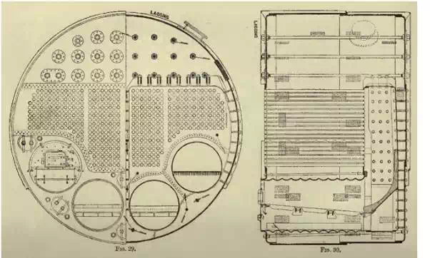
The end plates above the tubes and combustion chamber and below the furnaces are supported by long bar stays passing through the plates with nuts inside, and nuts and stiffening washers outside. The large stiffening washers are riveted to the plate as shown in Fig. 29. The front plate and tube plate between furnaces and tubes are similarly stayed.
Low type of high-pressure boiler.
The low type of cylindrical boiler, shown in Figs. 32 to (33) 34,
is fitted on board ships of the smaller classes, such as sloops, gun-vessels,
&c., and also where, in larger vessels, there is not sufficient room below
the vessel's protective deck to enable the high type of boiler to be fitted.
Boilers of this type in the Navy have generally given higher evaporative powers
than those just described.
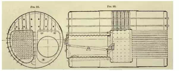
The sketches show a low boiler with
two furnaces, but in many vessels three furnace boilers of this type have been
fitted, and in a few cases four and even five furnaces.
In the large majority of such boilers the furnaces discharge into a common combustion
chamber, and such boilers have generally given very good results. The more
recent examples supplied for the Navy have been fitted with a divided
combustion chamber as recommended by the Admiralty Committee of 1892, so that
each furnace has a separate combustion chamber. Fig. 32 shows such a
boiler.
In this type it will be seen that the combustion chamber is wide, and that the
tubes, instead of returning above the furnaces to the uptake at the front of
the boiler as in the high type, are continued along the boiler at about the
same level as the furnaces, to the uptake which is situated at the other
end of the boiler. The path of the gases to the funnel is thus more direct than
with the high type. This type is sometimes known as the 'through-tube type.'
..........