Weld Defects and Weld Quality Testing:
Every weld joint is inspected by a team of trained inspectors for weld defects. Welding defects may arise due to lack of skill in welders, use of incorrect materials, or improper welding methods and ambient conditions.
The most common weld defects are as follows:
1. Lamellar tearing.
2. Crater cracks.
3. Inadequate cross section or insufficient penetration of weld pool.
4. Underbead cutting.
5. Gas entrapment within the weld pool.
6. Slag inclusions within the weld joint.
7. Overlaps.
8. Undercuts.
9. Lack of reinforcement.
10. Excessive reinforcement or extra deposition.
11. Lack of fusion within the weld pool.
The most commonly used non-destructive methods of weld quality inspection are discussed below.
• Visual Inspection: Visual inspection is carried out by a trained inspector, in which any surface defect is detected by the aid of a naked eye. Surface slag deposition, the incorrect shape of weld beads, incorrect alignment of plates and excessive reinforcement on the surface can be detected by visual inspection. However, all the undersurface defects require other methods of inspection that are discussed further.
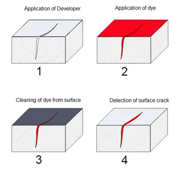
• Dye Penetrant Inspection (DPI): Surface cracks are most commonly detected by the dye penetrant method. First, the weld joint is cleaned so as to remove any slag or unwanted material on the surface of the welded joint. A layer of developer is sprayed over the weld joint. This is white in colour and aids the eye in the further steps. The dye is then sprayed over the weld joint. The colour of this dye is usually bright red because it is most noticeable to the human eye. After a sufficient waiting time, the weld joint surface is cleaned. The cleaning removes all the dye from the surface, however, the layer of developer remains. In the case of presence of any surface crack, the dye seeps in, hence after cleaning of the surface, the crack clearly appears red. It is in order to notice this with clarity that the developer is applied. The presence of any red lines indicate surface cracks, and corrective measures are hence taken.
Figure 9: Dye penetrant inspection.
• Magnetic Particle Testing: Smaller cracks are not noticeable in DPI tests. However, magnetic particle inspection reveals them clearly, due to the change in magnetic field at the cracks. In this test, the magnetic powder is spread on the weld joint to be tested. The alteration in magnetic field at a crack on a ferrous material, the magnetic particles accumulate along the length of the cracks, forming clusters at their vicinity. This provides a clear indication of surface cracks. The image below shows two regions of clusters of small cracks on a pipe.
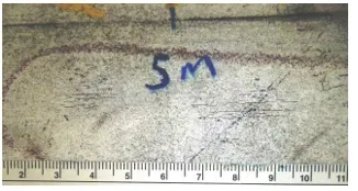
Figure 10:Cracks detected during magnetic particle testing on a metal pipe.
• Radiographic Testing: The method of radiographic testing is based on a fundamental principle of subjecting the test piece to a beam of radiation from one side, and capturing or recording the emitted radiation on a photographic plate on the other side of the test piece. This is where radiographic testing comes of great use in detection of subsurface weld defects. Any obstacle within the weld joint would change the radiation density in that area, which would be reflected on a photographic plate. Hence radiography is basically used to test the consistency of the weld metal. The following figure shows the detection of a surface and subsurface discontinuity on a photographic film.
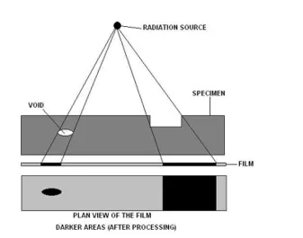
Figure 11: Schematic diagram of radiography test.
Both X-Rays and Gamma rays are used in radiography tests. Reading and interpreting weld defects from radiographic plates required skilled and experienced personnel who are specialised for the job.
• Ultrasonic Testing: Ultrasonic testing uses the same principle as that of radiographic testing, but with two major differences. First, use of ultrasonic radiations eradicates the health hazards related to harmful X-Rays and Gamma rays used in radiographic tests. Secondly, the recordings need not be processed as much as that of radiographic tests, because they are obtained in graphical format as discussed below.
A probe sends a beam of ultrasonic waves into the weld joint. The reflected waves are obtained on a graph on a computer screen. The first spike in the graph would be due to the reflection from the upper surface of the weld. The second spike (usually of lesser amplitude from the first) represents the wave reflected from the back (other) side of the plates. A presence of an obstruction within the welded area would also reflect some waves back to the probe, therefore cause the third spike of reduced amplitude than the spike caused due to the back side. This spike, however, appears before the spike from the back side appears. Added to that, since a number of waves now reaching the back side of the plates is reduced, the presence of a third spike due to a weld defect would also cause a reduction in the amplitude of the second wave, as shown in the schematic diagram below.
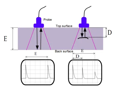
Figure 12: Schematic diagram of an ultrasonic test for weld defects.
The above illustration also helps us understand how ultrasonic testing can not only be used to detect the presence of a weld defect, but also detect the location of the defect. If the thickness of the plate is ‘E’, the distance between the spikes due to the front side and back side of a weld joint without defect would be ‘E’ on the linear distance scale on the graph. Similarly, the distance between the spike due to the upper surface and the spike due to the weld defect would reflect the depth from the surface at which the defect is located.
It is this property of ultrasonic testing that makes it the most widely used non-destructive
testing method for major welded structures in shipyards.
Today, classification societies have laid out norms not only on methods of welding but also on the standards of electrodes to be used for each type of joint, depending on its location on the ship. Major research works are being undertaken to predict the nature of weld distortions so as to develop welding methods to prevent rectification of structures due to welding induced stresses. It is this vast scope of research that makes welding an interesting field of study for researchers.