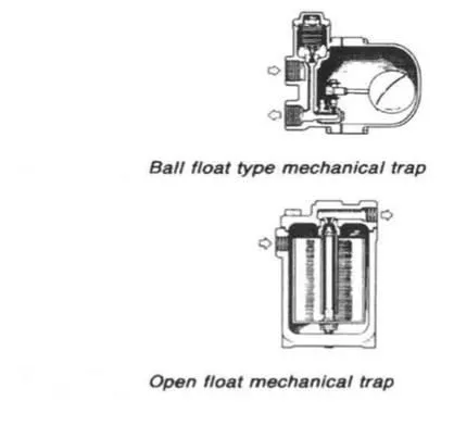
Figure 1: Ball float type mechanical trap & Open float mechanical trap
Steam traps
A steam trap is a special type of valve which prevents the passage of steam but allows condensate through. It works automatically and is used in steam heating lines to drain condensate without passing any steam. The benefit gained with a steam trap, is that steam is contained in the heating line until it condenses, thus giving up all of its latent heat. There are three main types which are the mechanical, the thermostatic and the thermodynamic. There is also the vacuum trap or automatic pump.
|
Figure 1: Ball float type mechanical trap & Open float mechanical trap
Mechanical traps have been installed with ball floats (Figure 1) or open floats (Figure 1) for control of a needle valve to release condensate.
Thermostatic traps
Thermostatic traps (Figures 2 : a, b and c) use the expansion of an oil-filled element, a bimetallic strip or flexible bellows to actuate a valve. As the condensate temperature rises in the oil filled element type (Figure a) element A expands to close the valve D. An adjustment screw E permits the valve to be set up for condensate release at a specific temperature.
Clearly in an application where the pressure varies, there could be a broad band of operation in which the trap would be either waterlogged or passing steam. With the bimetallic strip type (Figure b) deflection of the bimetallic strip when temperature increases, closes the valve. The device will work over a range of pressures without the need for re-adjustment and will operate satisfactorily under superheat conditions.
It is not particularly prone to damage by water hammer or vibration. In the flexible bellows type (Figure c) the bellows is filled with a mixture which boils at a lower temperature than does the steam. The trap self-compensates for operating pressure. It will be damaged if water hammer occurs and will burst if subjected to superheated steam.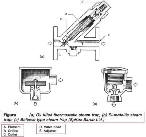
Figure 2: (a) Oil filled thermostatic steam trap; (b) Bi-metallic steam trap; (c) Bellows type steam trap (Spirax-Sarco Ltd.)
Thermodynamic steam trap
This type of trap uses the pressure energy of the steam to close the valve which consists of a simple metal disc. The sequence of operation is shown in Figure 3. In (i), disc A is raised from seat rings C by incoming pressure allowing discharge of air and condensate through outlet B. As the condensate approaches steam temperature it flashes to steam at the trap orifice. This means that the rate of fluid flow radially outwards under the disc is greatly increased. There is thus an increase in dynamic pressure and a reduction in static pressure. The disc is therefore drawn towards the seat. Due to this alone the disc will never seat.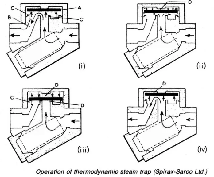
Figure 3: Operation of thermodynamic steam trap (Spirax-Sarco Ltd.)
However, steam can flow round the edge of the disc resulting in a pressure build up in the control chamber D as shown in (ii). When the steam pressure in chamber D acting over the full area of the disc (iii) exceeds the incoming condensate/steam pressure acting on the much smaller inlet area, the disc snaps shut over the orifice. This snap action is important. It removes any possibility of wire-drawing the seat, while the seating itself is tight, ensuring no leakage.
As shown in (iv) the incoming pressure will eventually exceed the control chamber pressure and the disc will be raised, starting the cycle all over again. The rate of operating will depend on the steam pressure and on the ambient air temperature. In practice, the trap will usually open after 15—25 s, the length of time open depending on the amount of condensate to be discharged. If no condensate has been formed, then the trap snaps shut immediately. From the foregoing it will be seen that the trap is never closed for more than 15—25 s, so condensate is removed virtually as soon as it is formed.
Vacuum or pumping traps
The layout of drain systems can often be improved by the use of automatic pumps, sometimes referred to as vacuum traps. Condensate can be drained by gravity more readily to local receivers and then pumped back to the engine room as required. Similarly engine room drains can be relieved of much back pressure by taking them to a low level hot well before pumping to a high level boiler feed tank.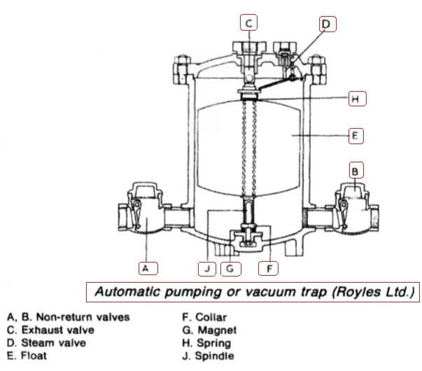
Figure 4 : Automatic pumping or vacuum trap (Royles Ltd.)
A, B. Non-return valves F. Collar C. Exhaust valve G. Magnet D. Steam valve H. Spring E. Float J. Spindle
A high level feed tank will enable the pumps to handle warm feed water and can improve the overall efficiency of the plant. A typical pumping trap is shown in Figure 4. When the trap is empty, the exhaust valve C is open and the steam valve D is closed. Water flowing into the trap through the non-return valve A raises the float E until it compresses the spring H, exerting a force which plucks the spindle J away from the magnet G so that the exhaust valve is projected into the closed position and the steam valve D is opened through the movement- of the lever. Steam is therefore admitted to the trap and drives out the water through the non-return valve B.
The float fails with the level of the water inside the trap and engages the collar F, pulling the spindle J down so that the exhaust valve opens and the steam valve closes. The cycle of operation is then repeated. Being float controlled, the trap operates only when water is flowing into it.
Maintenance of traps
A defective trap wastes steam and fails to ensure adequate heating. Poor heater performance can sometimes be traced to a defective steam trap. One remedy is to close in the steam outlet valve to perhaps half or quarter of a turn. Most traps can be regularly opened for inspection. The only exception is the thermodynamic type. When operating correctly this gives a characteristic 'click', usually at intervals of between 20 and 30 s so that its performance can be checked simply by listening.
Before inspecting any trap, it is advisable to check the strainer which should always be provided at the inlet of the trap. The contents of the strainer screen will give an indication of the cleanliness of the system. Fine dirt passing through the strainer is one of the chief causes of defective steam traps. Pieces of pipe scale or dirt jammed across the seat can prevent proper closure and if left for a period of time can give rise to wire drawing.
In most cases cleaning and reassembling should be sufficient to ensure satisfactory operation. If the thermodynamic type fails to operate after cleaning, then it could be that the disc and seat require lapping. Mechanical traps should be checked for defective floats and buckets and wear on any linkages, while the valves and seats should be renewed if necessary. In the case of thermostatic traps, the elements should be checked to ensure that they are sound. Particular care should be taken with the elements of bimetallic steam traps. Incorrect adjustment can give rise to excessive waterlogging or cause the traps to blow steam, while the elements themselves can sometimes assume a permanent 'set'.