Working of Electromagnetic brakes - Fail safe arrangement for Engine room cranes.
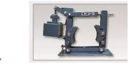
Basiclly, a lever which is connected to the arm which carries the brake shoes are pulled in when the circuit is denergized, it releases only when the circuit is energized and the drum will become free to move. Explained operation is given below. This is a fail safe arrangement as a power failure wil ensure the braes tighted on to the drum, The Shoes are of cast iron and other components are of fabricated steel. The lever is hinged on the main arm, which is connected to the side arm through a tie rod, and is stressed by a pre-loaded compression spring. The compression of the spring can be adjusted to set the braking torque to desired value. The brake liner of selected quality material is riveted to the shoes by aluminium rivets. A.C. solenoid with laminated magnetic sheet steel houses a copper magnetizing coil which is impregnated with Class F materials. The plunger which is connected to the lever, is drawn in to the coil, when it is energized with AC source. This loads the spring and releases the brake shoes from the brake drum. When the supply is cut off, the plunger is pulled out of the coil, and spring force clamps the brake shoes on the brake drum and the brake is applied.
Usually this kind of brakes are used in E/R cranes, motors and other heavy rotating machineries which needed to be stopped instantly, and needs to hold load.
Under voltage and over current trips
The Under Voltage trip stops you putting a generator that is not generating full voltage onto the board.
Checking of the trips:
I would always check the makers Instruction Manual for the specific breaker before trying to do anything.
As this is a procedure that is usually carried out for the Classification Society Special Survey of Electrical Equipment, and will usually be carried out by a specialist electrical contractor, often the licensed service agent for the Breaker Manufacturer. It would usually be carried out as part of the 5 yearly Special Survey during a drydock when the vessel would be on shore power.
No testing would normally be carried out with the Alternator running yet alone on load. The Breaker would have to be electrically isolated from the Generators and the Main Bus Bars to test it. So it would usually be "Racked out" of the Board.
Old Breakers have simple electo mechanical trips for overload and undervoltage, and can only be tested by current injection. This involves connected the low voltage, high current windings of a transformer across the breaker, the output current, delivered at only a few Volts, is adjusted until the breaker trips.
More Modern breakers have sophisticated Electronic devices to trip the breaker in addition to the electro mechanical system and sometimes these can be tested by adjusting the set points for undervoltage and over current to the actual operating conditions and thus causing the breaker to trip. However, these devices are often not accepted by Class or Statutory Surveyors who require the Electro Mechanical system to be working.
Testing the trips by changing the set points is only acceptable if you can prove that the calibration of the sensors is correct at the normal trip point.