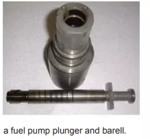
Jerk type fuel pumps having injection timings retarded-Why?
Fuel pumps plungers are machined to very fine tolerances, as is the matched barrel in which it reciprocates. This means that a plunger from one fuel pump cannot be used into another barrel from a different fuel pump, of same make and model.
Wear due to erosion (due to high pressure fuel as it spills) takes place on the top edge of the plunger and the edge of the helices and spill ports. This, together with the wear in the plunger and barrel, will lead to the injection timing becoming retarded, for which adjustment may have to be made.
Labyrinth seal fitted on the back surface of a compressor wheel of a turbocharger:
A labyrinth arrangement is fitted to the back of the compressor impeller to restrict the leakage of air to the gas side. It also prevents the oil being drawn into the compressor. Labyrinth seals use high rotational speed of the shaft to its advantage.
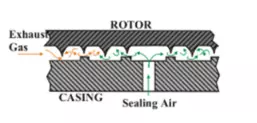
Labyrinth seals or glands are fitted to the shaft and casing to prevent the leakage of exhaust gas into the turbine end bearing, or to prevent oil being drawn into the compressor. To assist in the sealing effect, air from the compressor volute casing is led into a space within the gland. A vent to atmosphere at the end of the labyrinth
gives a guide to the efficiency of the turbine end gland. Discoloring of the oil on a rotor fitted with a roller bearing will also indicate a failure in the turbine end gland.
How centrifugal compressors handle air, where centriful pumps do not
Centrifugal pumps and compressors operates on the same principle of converting kinetic energy of the rotating impeller to pressure energy of the fluid it handles. The fluid particles are thrown out from the tip of the impeller with huge kinetic energies, which is converted to pressure energy by the special volute design of the casing. Both cent. pumps and compressors operates on same principle but have a different clearance levels, and impeller dimensions.
The performance of a centrifugal pump will be largely dependent upon the wear ring clearance. Wear ring clearance is the clearance between the impeller and the casing at the inlet side of the pump. If this clearance is high, the fluid inside the casing will be pumped back to the suction eye, reducing pump efficiency. For a normal centrifugal pump handling liquids, this clearance is relatively higher. For a centrifugal compressor, the wear ring clearance will be extremely small. This will allow handling of fluids of very low densities i.e, air .
A large impeller can create very high angular velocities at the impeller tips, which translates into high pressure energy of the fluid handled. The Auxiliary blowers for main engines and T/C blowers are centrifugal with large impeller diameters because of this reason. Large rotational speeds also increases the rate of energy transfer to the fluid handled, which also results in handling of light fluids.
Why nimonic coating is provided on valve stem of exhaust valves of marine engines??
The purpose of Nimonic coating in exhaust valve of modern marine engines is to prevent hot corrosion of the valve stems, increase valve life and to minimize the effect of valve burning.
Modern marine engines, operating on HFO with a bore greater than 300mm, the one propelling my current vessel is MAN B&W 6G50ME, operates with a relatively high exhaust temperatures of 350-400 deg Celsius. Under this temperature the uncoated valve stems may give up their strength, leading to overall reduction in valve life. Also under high temperatures the valves stems are subjected to hot corrosion. Nimonic have a very high temperature stability and resists hot corrosion.
Full nemonic coated valves are also available from engine manufacturers , which will increase overall lifetime of the valve, but increase the cost marginally.
Valve seats are usually treated with a harder alloy compound, stellite.
MAN B&W are now introducing DURA SPINDLE valves with W seats to still increase the overall life, with a promised run time of 20000 hours.
Purpose of an economiser on board a ship
An economiser, as the name suggests increases the overall economy of the main propulsion plant. The heat from burning fuel in main engine is mostly used to move the piston and thereby create the main propulsion onboard. Some of this heat energy cannot be used in the process, as the process is never isothermal. This heat energy is used to produce steam onboard, using economisers.
The process is simple. The unused heat from the main engine exhaust is transferred to water in the economiser, which produces the necessary steam for the propulsion plant. When economiser is absent, this head energy need to be provided by burning extra fuel in boilers, which costs $$$. So economiser in the end, increases the overall heat efficiency or the ECONOMY of the propulsion plant.