
Vapor Compression Refrigeration System
Vapor-compression refrigeration, in which the refrigerant undergoes phase changes, is one of the many refrigeration cycles and is the most widely used method for air-conditioning of buildings and automobiles. It is also used in domestic and commercial refrigerators, large-scale warehouses for chilled or frozen storage of foods and meats, refrigerated trucks and railroad cars, and a host of other commercial and industrial services. Oil refineries, petrochemical and chemical processing plants, and natural gas processing plants are among the many types of industrial plants that often utilize large vapor-compression refrigeration systems.
The figure shows the basic components of a vapor compression refrigeration system.
As shown in the figure the basic system consists of an evaporator, compressor, condenser and an expansion valve. The refrigeration effect is obtained in the cold region as heat is extracted by the vaporization of refrigerant in the evaporator. The refrigerant vapor from the evaporator is compressed in the compressor to a high pressure at which its saturation temperature is greater than the ambient or any other heat sink. Hence when the high pressure, high-temperature refrigerant flows through the condenser, condensation of the vapor into liquid takes place by heat rejection to the heat sink. To complete the cycle, the high-pressure liquid is made to flow through an expansion valve. In the expansion valve the pressure and temperature of the refrigerant decrease. This low pressure and low-temperature refrigerant vapor evaporates in the evaporator taking heat from the cold region. It should be observed that the system operates on a closed cycle. The system requires input in the form of mechanical work. It extracts heat from a cold space and rejects heat to a high-temperature heat sink.
Vapor Compression Cycle -Working Diagram
A refrigeration system can also be used as a heat pump, in which the useful output is the high-temperature heat rejected at the condenser. Alternatively, a refrigeration system can be used for providing cooling in summer and heating in winter. Such systems have been built and are available now
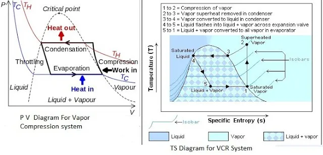
PV And TS Diagram For Vapor Compression System
Most of the modern refrigerators work on this cycle, in Its simplest form, there are four fundamental operations required to complete one cycle.
(a) Compression
(b) Condensation
(c) Expansion
(d) Vaporization
a) Compression
The low-pressure Vapour in the dry state is drawn from the evaporator during the suction stroke of the compressor. During compression Stroke, the pressure and temperature increase until vapor temperature is greater than the temperature of condenser cooling medium (air or water)
At point 1 in the diagram, the circulating refrigerant enters the compressor as a saturated vapor. From point 1 to point 2, the vapor is isentropically compressed (i.e., compressed at constant entropy) and exits the compressor as a superheated vapor.
b) Condensation
When the high-pressure refrigerant vapor enters the condenser heat flows from the condenser to the cooling medium thus allowing the vaporized refrigerant to return to the liquid state.
From point 2 to point 3, the vapor travels through part of the condenser which removes the superheat by cooling the vapor. Between point 3 and point 4, the vapor travels through the remainder of the condenser and is condensed into a saturated liquid. The condensation process occurs at essentially constant pressure.
c) Expansion
After condenser the liquid refrigerant is stored in the liquid receiver until needed. From the receiver it passes through an expansion valve where the pressure is reduced sufficiently to allow the vaporization of liquid at a low temperature of about -10°C.
Between points 4 and 5, the saturated liquid refrigerant passes through the expansion valve and undergoes an abrupt decrease of pressure. That process results in the adiabatic flash evaporation and auto-refrigeration of a portion of the liquid (typically, less than half of the liquid flashes).
d) Vaporization
The low-pressure refrigerant vapor after expansion in the expansion valve enters the evaporator or refrigerated space where a considerable amount of heat IS absorbed by it and refrigeration is furnished.
Between points 5 and 1, the cold and partially vaporized refrigerant travels through the coil or tubes in the evaporator where it is vaporized by the warm air (from the space being refrigerated) that a fan circulates across the coil or tubes in the evaporator.
The resulting refrigerant vapor returns to the compressor inlet at point 1 to complete the thermodynamic cycle.