Diesel Fuel Injection
Basic Principles
The performance of diesel engines is heavily influenced by their injection system design. In fact, the most notable advances achieved in diesel engines resulted directly from superior fuel injection system designs. While the main purpose of the system is to deliver fuel to the cylinders of a diesel engine, it is how that fuel is delivered that makes the difference in engine performance, emissions, and noise characteristics.
Unlike its spark-ignited engine counterpart, the diesel fuel injection system delivers fuel under extremely high injection pressures. This implies that the system component designs and materials should be selected to withstand higher stresses in order to perform for extended durations that match the engine’s durability targets. Greater manufacturing precision and tight tolerances are also required for the system to function efficiently. In addition to expensive materials and manufacturing costs, diesel injection systems are characterized by more intricate control requirements. All these features add up to a system whose cost may represent as much as 30% of the total cost of the engine.
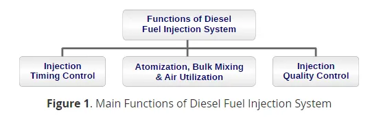
The main purpose of the fuel injection system is to deliver fuel into the cylinders of an engine. In order for the engine to effectively make use of this fuel:
i.Fuel must be injected at the proper time, that is, the injection timing must be controlled and
ii. The correct amount of fuel must be delivered to meet power requirement, that is, injection metering must be controlled.
However, it is still not enough to deliver an accurately metered amount of fuel at the proper time to achieve good combustion. Additional aspects are critical to ensure proper fuel injection system performance including:
· Fuel atomization—ensuring that fuel atomizes into very small fuel particles is a primary design objective for diesel fuel injection systems. Small droplets ensure that all the fuel has a chance to vaporize and participate in the combustion process. Any remaining liquid droplets burn very poorly or are exhausted out of the engine. While modern fuel injection systems are able to produce fuel atomization characteristics far exceeding what is needed to ensure complete fuel evaporation during most of the injection process, some injection system designs may have poor atomization during some brief but critical periods of the injection phase. The end of the injection process is one such critical period.
· Bulk mixing—While fuel atomization and complete evaporation of fuel is critical, ensuring that the evaporated fuel has sufficient oxygen during the combustion process is equally as important to ensure high combustion efficiency and optimum engine performance. The oxygen is provided by the intake air trapped in the cylinder and a sufficient amount must be entrained into the fuel jet to completely mixed with the available fuel during the injection process and ensure complete combustion.
· Air utilization—Effective utilization of the air in the combustion chamber is closely tied to bulk mixing and can be accomplished through a combination of fuel penetration into the dense air that is compressed in the cylinder and dividing the total injected fuel into a number of jets. A sufficient number of jets should be provided to entrain as much of available air as possible while avoiding jet overlap and the production of fuel rich zones that are oxygen deficient.
The primary purposes of the diesel fuel injection system are graphically represented in Figure 1.
Many specialized concepts and terms are used to describe the components and the operation of diesel fuel injection systems. Some of the more common of these include :
Nozzle refers to the part of the nozzle body/needle assembly which interfaces with the combustion chamber of the engine. Terms like P-Type, M-Type, or S-Type nozzle refer to standardized dimensions of nozzle parameters, as per ISO specifications.
Nozzle holder or injector body refers to the part the nozzle is mounted on. In conventional injection systems this part mainly served the nozzle mounting and nozzle needle spring preloading function. In common rail systems, it contains the main functional parts: the servo-hydraulic circuit and the hydraulic actuator (electromagnetic or piezoelectric).
Injector commonly refers to the nozzle holder and nozzle assembly.
Start of injection (SOI) or injection timing is the time at which injection of fuel into the combustion chamber begins. It is usually expressed in crank angle degrees (CAD) relative to TDC of the compression stroke. In some cases, it is important to differentiate between the indicated SOI and actual SOI. SOI is often indicated by an easily measured parameter such as the time that an electronic trigger is sent to the injector or a signal from a needle lift sensor that indicates when the injector needle valve starts to open. The point in the cycle where this occurs is the indicated SOI. Due to the mechanical response of the injector, there can be a delay between the indicated SOI and the actual SOI when fuel exits the injector nozzle into the combustion chamber. The difference between the actual SOI and indicated SOI is the injector lag.
Start of delivery. In some fuel systems, fuel injection is coordinated with the generation of high pressure. In such systems, the start of delivery is the time when the high pressure pump starts to deliver fuel to the injector. The difference between start of delivery and SOI is affected by the length of time it takes for a pressure wave to travel between the pump and injector and is influenced by the length of line between the high pressure pump and the injector and by the speed of sound in the fuel. The difference between the start of delivery and SOI can be referred to as injection delay.
End of injection (EOI) is the time in the cycle when fuel injection stops.
Injected fuel quantity is the amount of fuel delivered to an engine cylinder per power stroke. It is often expressed in mm3/stroke or mg/stroke.
Injection duration is the period of time during which fuel enters the combustion chamber from the injector. It is the difference between EOI and SOI and is related to injection quantity.
Injection pattern. The rate of injection of fuel often varies during the injection duration period. Figure 2 shows three common rate shapes: boot, ramp and square. Opening rate and closing rate refers to the gradients in the rate of injection during needle nozzle opening and closing events, respectively.
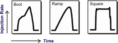
Figure 2. Common injection rate shapes
Multiple injection events. While conventional fuel injection systems employ a single injection event for every engine cycle, newer systems can use multiple injection events. Figure 3 defines some of the common terms used to describe multiple injection events. It should be noted that the terminology is not always consistent. The main injection event provides the bulk of the fuel for the engine cycle. One or more injections before the main injection, pre-injections, provide a small amount of fuel before the main injection event. Pre-injections can also be referred to as pilot injection. Some refer to a pre-injection that occurs a relatively long time before the main injection as a pilot and one that occurs a relatively short time before the main injection as a pre-injection. Injections after the main injections, post-injections, can occur immediately after the main injection (close post-injection) or a relatively long time after the main injection (late post-injection). Post-injections are sometimes called after-injections. While there is considerable variation in terminology, a close post-injection will be referred to as a post-injection and a late post-injection as an after-injection.
Figure 3. Multiple Injection Events
The term split injection is occasionally used to refer to multiple injection strategies where a main injection is split into two smaller injections of approximately equal size or into a smaller pre-injection followed by a main injection.
Unintended post-injections can occur in some fuel injection systems when the nozzle momentarily re-opens after closing. These are sometimes referred to as secondary injections.
Injection pressure is not used consistently in the literature. It may refer to the mean pressure in the hydraulic system for common rail systems, or to the maximum pressure during an injection (peak injection pressure) in conventional systems.
With a few exceptions, fuel systems can be broken down into two major component groups:
· Low pressure side components—These components serve to safely and reliably deliver fuel from the tank to the fuel injection system. Low pressure side components include the fuel tank, fuel supply pump and the fuel filter.
· High pressure side components—Components that create high pressures, meter and deliver the fuel to the combustion chamber. They include the high pressure pump the fuel injector and fuel injection nozzle. Some systems may also include an accumulator.
Fuel injection nozzles can be categorized as hole-type or throttling pintle type and as either a closed or open. Closed nozzles can be actuated hydraulically using a simple spring-biased mechanism or using servo control. Open nozzles as well as some newer closed nozzle injector designs can be directly actuated.
Metering of the injected fuel amount is commonly carried out in either the high pressure pump or the fuel injector. A number of different fuel metering approaches exist including: pressure metered at a constant time interval (PT), time metered at a constant pressure (TP) and time/stroke metered (TS).