Balancing Machines - Types, Classification, and Methods
The goal of rotor balancing is to reduce unbalance enough such that it can operate properly once installed on site. Reducing unbalance reduces vibration and increases efficiency and life of the rotor and bearings. Additionally, during production and repair, it is necessary to balance rotors before full assembly because there may be limited access to the rotor.
A balancing machine is used to determine the location and amount of unbalanced masses on a rotor. The rotor is mounted on the machine bearings and the machine spins the rotor. Soft bearing machines measure the displacement of the ends of the rotor and bearings. The machine measures this displacement and the phase angle, then computes the unbalance present. Balancing machines then provide the operator with corrections to be made to the rotor via addition or subtraction of weight.
Why the Need for a Balancing Machine?
When assessing a rotor, unbalance cannot be visually identified. A hole or added weight on a rotor may be there from an initial balancing of the rotor, not the cause of unbalance. The only way to assess unbalance is via the vibration or the force it generates.
In maintenance and overhaul of rotating equipment, there are many cases when it is impractical to attempt in-place balancing because weight corrections cannot be made. This is true for many pumps and totally enclosed motors as well as turbines and some centrifuges. Also, the process of repairing a rotor causes gross unbalance which requires balancing prior to reassembling, thereby eliminating possible damage when starting up the machine. A balancing machine is used to balance parts before re-installation, ensuring smooth operation of the machine. A balancing machine can be an extremely valuable asset to any maintenance department that repairs pumps, motors and other rotating equipment. It can save costs due to delays by eliminating the need to send parts to outside specialists to be balanced. Often the savings on one job alone can justify the expense for a balancing machine.
Manufacturers of rotating mechanical equipment must have assurance that their product will operate smoothly when installed at the final site. One of the prime concerns is the balancing quality of the rotating components. Through experience, the manufacturer can established a tolerable limit of unbalance which can be accepted in a particular machine. The manufacturer knows that by exceeding this limit, customer complaints and machinery downtime will reflect in the quality of his product. To meet this situation, parts will be balanced at the time of manufacturer, in most instances, prior to assembly and sometimes trim balanced as an assembly.
Types of Balancing Machines
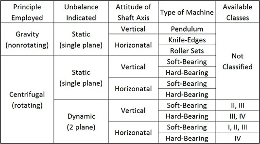
Balancing Machines are usually classified according to the principle employed, how the unbalance is indicated, type of machine, method of operation, etc.
Classification of Centrifugal Balancing Machines
Centrifugal balancing machines may be categorized by the type of unbalance a machine is capable of indicating (static or dynamic), the attitude of the journal axis of the workpiece (vertical or horizontal), and the type of rotor-bearing-support system employed (soft-bearing or hard-bearing). In each category, one or more classes of machines are commercially built.
Class I - Displacement Indicating Balancing Machines
Machines in this class are usually of the soft-bearing type. They do not usually indicate unbalance directly in weight units (such as ounces or grams in the actual correction planes) but indicated displacement and / or velocity of vibration at the bearings. The instrumentation does not directly indicate the amount of weight which must be added or removed in each of the correction planes. Balancing with this type of machines involves the use of portable instrumentation. Amount and angular location of correction weights are determined by performing simple vector calculations or by using a calculator to perform two-plane balancing operations.
Class II - Calibratable Balancing Machines Requiring a Balanced Prototype
Machines in this class are of the soft-bearing type using instrumentation which permits plane separation and calibration for a given rotor type, if a balanced master or prototype rotor is available.
Class III - Calibratable Balancing Machines Not Requiring a Balanced Prototype
Machines in this class are of the soft-bearing type. Any (unbalanced) rotor may be used in plane of a balanced master rotor. In turn, plane separation and calibration can be achieved for rotors without trial and error. This class includes soft-bearing machines with electrically driven shakers fitted to the vibratory part of their rotor supports. Microprocessor techniques allow this type to be calibrated without spinning the rotor and represents the latest in balancing technology.
Class IV - Permanently Calibrated Balancing Machines
Machines in this class are of the hard-bearing type. They are calibrated by the manufacture for all rotors falling within the weight and speed range of a given machine size. These machines indicate unbalance in the first run without individual rotor calibration. This accomplished by the incorporation of an analog computer into the instrumentation associated with the machine. This type of balancing requires a very substantial machine foundation to eliminate vibration interference from other equipment.
Static, Non-Rotating Balancing
The first principle group is based on the fact that a body free to rotate will seek a position where its center of gravity is lowest. Thus, the heavier side of the the rotor will seek the lowest position, automatically indicating the angular position of the unbalance weight. The magnitude of unbalance is determined experimentally by adding weight in the form of wax or putty to the light side of the disc until it is in balance, or when the disc no longer rotates. The roller stand, pendulum and horizontal ways can be used to determine static unbalance via gravity.
The roller stand in Figure A is optimal because it allows for run-out measurements to be taken and does not require precise alignment like the horizontal ways in Figure C. In Figure B, a disc is supported on a flexible cable or alternately, a ball-and-socket device which coincides with the center of the disc and slightly above the normal plane through the center of gravity. The heavy side will tend to seek a lower level than the light, thereby indicating the angular position of the unbalance. The disc is balanced by adding weight to a point diametrically opposed to the spot until the disc is level, as indicated by a circular "bubble" or level at the center of the balancing machine. Variations of these methods are used.
Static (non-rotating) balancing is satisfactory for:
Rotors having low length/diameter ratios operating at low speeds
Narrow rotors operating at moderate speeds
High-speed rotors which are to be assembled to a shaft and later balanced as an assembly
Dynamic Balancing Machines, Soft-Bearing vs. Hard-Bearing
Two-plane balancing machines, or dynamic balancing machines, are used for correcting static and dynamic unbalance. The two general types of dynamic balancing machines that have received the widest acceptance are the "soft" or flexible bearing machine and the "hard" or rigid bearing machine. While there is really no difference between the bearings used, the machines have different types of suspensions.
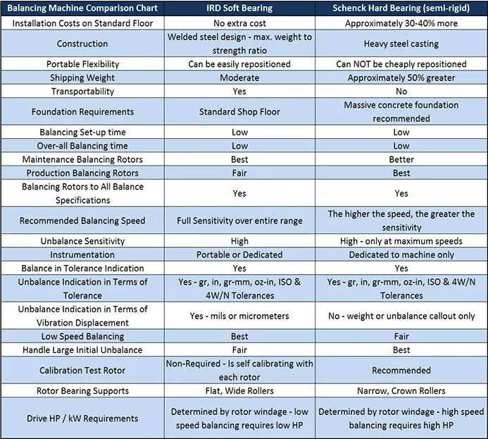
Soft-Bearing Balancing Machines
The soft-bearing machine derives its name from the fact that it supports the rotor to be balanced on bearings that are free to move in at least one direction, usually horizontally or perpendicularly to the rotor axis. The theory behind this style of balancing is that the rotor behaves as if suspended in mid-air while the movements of the rotor are measured. The mechanical design of a soft-bearing machine is slightly more complex, but the electronics involved are relatively simple compared to the hard-bearing machines. The design of the soft-bearing balancing machine allows for it to be placed almost anywhere, as the flexible work supports provide a natural isolation from nearby activity. This also allows for the machine to be moved without affecting the calibration of the device, unlike the hard-bearing machines.
The resonance of the rotor and bearing system occurs at one-half or less of the lowest balancing speed. Balancing is done at a frequency higher than the resonance frequency of the suspension.
Besides the fact that a soft-bearing balancing machine is a portable one, it provides the added advantages of having a higher sensitivity than the hard-bearing machines at lower balancing speeds; the hard-bearing machines measure force which typically requires a higher balancing speed. An additional benefit is that our soft-bearing machines measure and display the actual movement or displacement of the rotor while it is spinning which provides a built-in means of validating the fact that the machine is responding properly and the rotor is balanced correctly.
The major advantage of soft-bearing machines is that they tend to be more versatile. They can handle a wide range of rotor weights on one size of a machine. No special foundation is required for insulation and the machine can be moved without having to obtain a re-calibration from a specialist.
Soft-bearing balancing machines, like hard bearing machines, can balance most horizontally oriented rotors. However, balancing of an overhung rotor requires the use of a negative load hold-down attachment piece.
The image above shows IRD®'s soft bearing balancing machine. Notice that the orientation of the bearing system allows for the pendulum to swing back and forth with the rotor. The displacement is recorded by the vibration sensor and later used to calculate the unbalance present.
Hard-Bearing Balancing Machines
Hard-bearing balancing machines have stiff work supports and rely on sophisticated electronics to interpret the vibrations. This requires a massive, stiff foundation where they must be permanently set and calibrated in place by the manufacturer. The theory behind this balancing system is that the rotor is fully constrained and the forces that the rotor puts on the supports are measured. Background vibration from adjacent machines or activity on the work floor can affect balancing results. Commonly, hard-bearing machines are used in manufacturing production operations where a fast cycle time is required.
The major advantage to hard-bearing machines is that they tend to provide a quick unbalance readout, which is useful in high speed production balancing.
A limiting factor of hard-bearing machines is the required balancing speed of the rotor during testing. Because the machine measures unbalance force of the rotating rotor, the rotor must be spun at a high speed to generate enough force to be detected by the stiff suspensions.
Whip
Regardless of which horizontal balancing machine used, analysis of whip may be necessary when balancing long, thin rolls, or other flexible rotors. Whip is a measurement of the deformation or bending of a flexible rotor. If you suspect that you may need to measure whip, check with our technical support and we will determine whether or not a whip indicator is necessary for your application.
Balancing Methods
A long time ago, it was essential for a balancing technician to be able to perform all of the balancing calculations, and human error was a potential contributing factor in all balancing situations. Now, everything is automated. When using IRD® Balancing's soft bearing balancing machines, one simply follows the instructions on the screen, step by step. This steps are as follows:
1. Chose the Rotor Setup.
Our Balancing Instruments are set up to handle the 9 different rotor configurations. Once you choose the rotor configuration, you are instructed to spin the rotor and take a measurement reading, then stop the rotor.
2. Calibration of the Machine with the Rotor
The Balancing Instrument will then instruct the user to add a known weight to the first correcting location on the left hand side, enter the illustrated required dimensions, spin up the rotor and take a measurement, stop the rotor, then remove the left hand weight and place it in the right hand correction plane and repeat. Stop the rotor and remove the known weight. The instrument then uses these measurements to calibrate itself.
3. Balancing the Rotor
The Balancing Instrument now displays both the left and right hand correction amounts and the angular location of the correction weights for the addition or subtraction (user specified) of material.
That's it! Advancements in technology have turned balancing into a fairly easy task, making it applicable and necessary in every machine shop!
The video below is a demonstration of the Model 295 Balancing Instrument. Note, this is the same video as the one of the homepage.
The Alternative to Machine Balancing - Field Balancing
Many rotors can often be balanced in place, running at their own operating speed, with minimum disassembly. To balance in place, of course, a basic requirement is that the rotor has to be accessible to make corrections. Machines such as fans and blowers are good candidates. Totally enclosed motor armatures and pump impellers are not.
The technique of balancing in place is referred to as Field Balancing and it offers some distinct advantages including:
Balancing is performed on the complete assembled machine and compensates for the assembly tolerances.
Costly and time-consuming disassembly to transport the rotor to a balancing machine is eliminated.
The effects of temperature, pressure, distortion and other environmental influences can be incorporated.
The resultant vibration can be the tolerance applied to the rotor, rather than the published balance tolerances normally used in a balancing machine. This is particularly advantageous if the supporting structure is close to a resonance. The unbalance in the rotor may have to be adjusted to abnormally fine levels to minimize the resultant resonant structural vibration.
Since the rotors are balanced in place, a balancing machine does not have to be purchased.
Modern instruments such as vibration analyzers, data collectors and portable balancers provide accurate information to assist in the balancing process. The vibration level measured at the rotating speed frequency is used as an indicator of the amount of unbalance. The location is determined by measuring the phase. Phase, (the relative motion of one part of a machine to another) is measured by means of a stroboscopic light or by an indicator in the instrument, triggered by a photocell.
It is imperative that the vibration measured is a result of the unbalance and not some other exiting force. Only a detailed, thorough, analysis can identify where the vibration measured is coming from. Many sources of vibration can occur at the rotating speed frequency.
When field balancing, trial weights for balance computation and permanent weights for final correction are normally added to the rotor. Care should be taken when attaching weights. They should be attached securely so that they cannot 'fly off' when the machine is operating. They not only constitute a personnel safety hazard but also can cause damage. Loose balance weights rattling around inside a turbine for example can wreck the machine.
Our field balancing instruments are the Model 246 & the Model 258.