Rotodynamic Machine
a mechanism for converting the energy of a moving liquid or gas into the energy of a rotating shaft (for example, a hydroturbine), or vice versa (for example, a ventilator). The power transfer to or from the flow takes place as a result of the change in the angular momentum of the fluid or gas during its passage through the rotor of the machine.
Rotodynamic machines were known even before the Common Era (the reaction steam turbine of Hero of Alexandria and the hydraulic turbines of the ancient Romans); water-driven and wind-driven mills were in use long ago. Gas turbines and the axial compressor were developed in the late 19th century. The fundamental theory of rotodynamic machines was developed by L. Euler, who was the first to describe the basic hydromechanical flow sheet of their operation. The theory of latticed wing sections, which is the basis of the blade design for rotodynamic machines, was created by the Russian scientists N. E. Zhukovskii and S. A. Chaplygin.
Rotodynamic machines are classified in terms of design as single-stage and multistage types. A single-stage machine consists of a rotor and devices for the intake and discharge of fluid. In multistage machines a distinction is made between the end and intermediate stages. The end stages (input and output) differ in design: the former consists of an intake device with a stator and a rotor, and the latter consists of a discharge device following the final rotor. The intake is designed to create a velocity moment in the fluid at the input to the rotor. The discharge acts to reduce the kinetic energy of the flow at the output of the machine, thereby improving its efficiency. The intermediate stages are alike and consist of a rotor and a stator. The rotor is the main element by which the machine converts energy; it consists of blades attached to a hub (boss), which is connected to a shaft.
The shape and design of the blades depend on the purpose, the conditions under which the working process takes place, the durability requirements, and the technology of fabrication. The relatively long blades of axial turbines (the ratio of the mean diameter on which the blades are mounted to the blade length is less than 12) have a spiral twist along the radius. Such a shape takes into account the variation in the peripheral velocity of the blades and in the flow velocity interacting with them along the radius. If the blades are not manufactured in one piece with the central disk, they are connected to it by welding or by mechanical means, and they may have variable pitch (for regulation). The blade length ranges from 5-7 mm for small turbines up to 15 m or more for wind engines.
Rotodynamic machines are classified as axial, radial-axial (diagonal), and radial, depending on the direction of flow in the rotor. According to principle of operation, they are classified as impulse and reaction types. In the first type, the pressure of the flow at the rotor’s input and output is the same and is equal to atmospheric pressure, pressure, and in the second type the pressures at the input and the output are different.
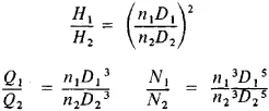
The power of a rotodynamic machine is adjusted by changing the flow rate of the fluid or gas in several ways. For example, the flow rate in hydroturbines can be altered by rotating the blades of the stator or rotor. Hydraulic similarity makes it possible to obtain not only the characteristics of individual rotodynamic machines but also those of various types of machines. The relationships among the shaft power N, the head H, the speed of rotation n, the flow rate Q, and the characteristic dimension of the flowthrough part D of two geometrically similar hydroturbines are given by the formulas
Rotodynamic machines are designed to operate on moving liquids (water and oils), gas, and steam; they are correspondingly called hydromachines, gas turbines, and steam turbines. (For the technical characteristics and design of such machines, seeWIND ENGINE, AIRSCREW, and PELTON WHEEL.)