Practical Difficulties of Topology Optimization for AM
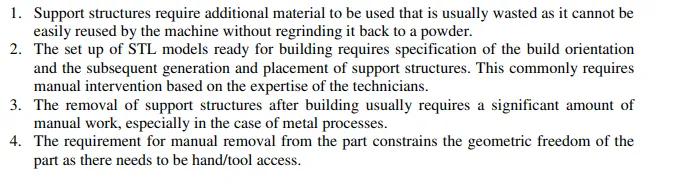
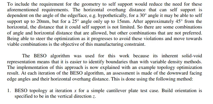
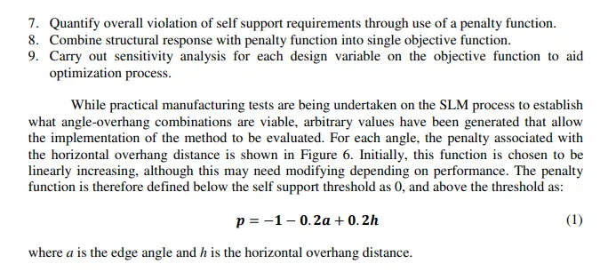
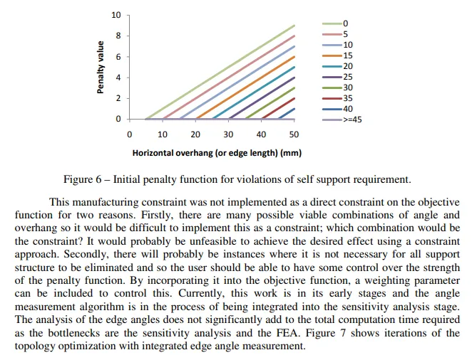
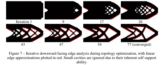
Topology optimization is a powerful approach for determining the best distribution of material within a defined design domain. Often, the optimized topology is complex and due to manufacturing constraints commonly requires either simplification following the optimization process or constraining of the design space to only allow manufacturable designs. AM enables the manufacture of the topology irrespective of the complexity and the cost of production does not usually increase with complexity. In fact, sometimes the cost can decrease with increased complexity due to reduced support structure requirement. As pointed out in a recent paper by Sigmund [11], optimal stiffness design favors very fine microstructure, which is inherently very complex. Depending on the scale of the designed component, it is difficult to determine the most suitable mesh size in advance to achieve this structure within the manufacturing limits. For traditional manufacturing routes it is usually more expensive to manufacture greater complexity and hence a high degree of complexity is usually undesired. This means that sub-optimal components are manufactured. With AM, there is the capability to manufacture very complex topologies and so there is no reason to prohibit the creation of this complexity.
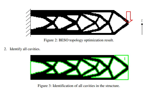
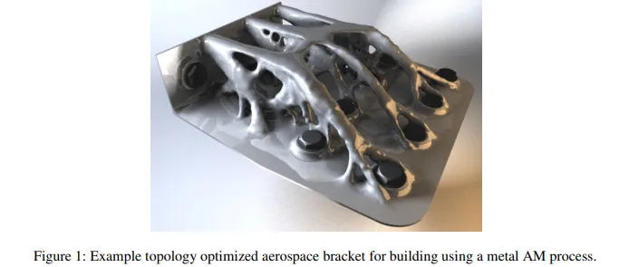
This leads to some practical difficulties when implementing topology optimization for AM. Firstly, the optimum topology can only be determined if the mesh allows the representation of it. It is well known that as the mesh is refined, further detail emerges and the optimality of the topology improves. For topology optimization, it is usual for each finite element with the design domain to be defined as a design variable, allowing a variation in density (homogenization, SIMP) or void-solid (BESO). Each member of the structure should have at least 2-3 finite elements across its thickness to ensure accurate calculation of the displacement and this has implications for the total number of design variables in the model. Figure 1 shows an example of a topology optimization carried out on an aerospace bracket. Components similar to this have been built using the metal selective laser melting (SLM) process [12] without any requirement
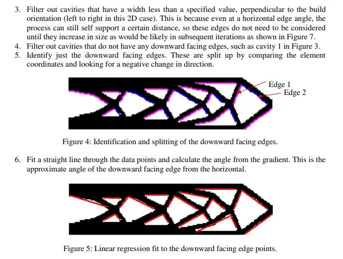
for modification. Some support structures are required to support large overhangs, but the topology itself is simply the smoothed optimization result using the SIMP method. Some fine features can be seen in this component, but the minimum feature size for the manufacturing process was far from being utilized. The low minimum feature sizes commonly achievable with AM means that a very high number of design variables are needed to represent the topology of maximum complexity. Currently, this is prohibitive for anything but the optimization of a very small component and so it is no longer the manufacturing stage that is the limiting factor in the realization of optimal designs; it is the design stage.
There are several actions that could be carried out to improve the efficiency of the topology optimization process for AM. Firstly, a hard-kill element elimination approach could be adopted where elements that have remained at very low modulus for a number of optimization iterations are completely removed from the model thereby reducing the number of finite elements. This, though, could encourage a worse result as the elements cannot be returned as the optimization continues. A second approach could be to use iterative remeshing thereby only refining where required and coarsening where a fine mesh is no longer needed. There have been several implementations of this approach in the literature in both 2D and 3D [13-21], and to the author’s knowledge a single commercial implementation, in the software TOSCA by FE Design [22]. This commercial implementation is very limited, allowing only refinement and derefinement in just 2 levels, and does not provide the level of remeshing required for AM optimization. A remeshing method specifically intended for AM has been proposed by [23] which has been coupled with a BESO algorithm. This offers great potential for efficiently taking full advantage of the AM complexity freedom. A third approach could be to use boundary based topology optimization methods such as the level set method [24]. The design variables are then only the boundaries, rather than the finite elements within the volume. Coupling with the XFEM analysis technique, as reported by [25,26], reduces the dependency of the result on the starting mesh.
It could be argued that it would not be worth the added computational expense to improve the optimality of the result only by a modest amount. However, for many practical applications, especially for aerospace, the use phase of the component is by far the most costly in terms of fuel requirement, and even modest weight savings result in a huge overall cost saving over the vehicles’ lifespan. This can justify the added computation time at the design stage.
Manufacturing Constraints
While the manufacturing constraints for AM are much less significant than traditional manufacturing routes there are still some that require consideration. Many of the AM constraints could be better termed manufacturing considerations, as they do not necessarily constrain the design. The need for scaffold structures to support large overhangs is dependent on the specific AM process used, as some do not require support structures at all. Up to a point, the processes that require supports, can self-support so long as the overhang is above a particular angle to the horizontal. With some of the metal processes, such as SLM, structures are required primarily to restrict curling/warping of the melted powder due to high temperature gradients, rather than to provide mechanical support. The need for support structures is also dependent on the geometry and often consideration is given to modifying the design to make it self-supporting. The main advantage of this is to reduce the post processing requirement of removing the support structures from the designed component, which is commonly a manual task, but a potential reduction in material usage is also a benefit. Some processes, such as fused deposition modeling (FDM) [27], have water soluble supports which significantly reducing the post processing burden. Other manufacturing constraints are build accuracy, surface finish and z-direction mechanical properties, but these have less relevance to the topology of the component and so will not be discussed here.
As mentioned in the previous section, depending on the specific component application, weight savings can be the primary objective rather than a reduction in manufacturing costs, due to energy use during the component use phase. In these cases, it would not be sensible to increase the weight of the component to reduce manufacturing costs, by reducing the amount of support structure. For applications where the manufacturing costs are more significant, then this could be useful. As yet, to the authors’ knowledge, there has been no research on methods for incorporating specific AM manufacturing constraints into the topology optimization process. The only existing applicable method is the minimum member thickness constraint [28-30] which is applicable to the minimum feature size constraint for the AM processes. This constraint is commonly found in commercial software such as Optistruct by Altair [31] and Nastran by MSC [32]. A maximum overhang constraint would need to be based on the maximum horizontal overhang distance and the angle of the overhang. A maximum thickness constraint as devised by [33,34] and an instance of which has recently been added to Optistruct intended for casting purposes, has some relevance to this issue. By limiting the maximum thickness of the members, it would be expected that this would result in an increase in the quantity of members. This then should reduce the horizontal overhang distance between members, thereby reducing the amount of support structure required. However, it would be difficult to know what specific maximum member thickness value to use in advance and it would likely require several runs to adjust this parameter. It is also unlikely that this would completely eliminate the need for any support material as it does not penalize large unsupported cavities edges.
Recent work by [35,36] has investigated the effect of varying the optimization parameters of a BESO algorithm, specifically the checkerboard filter radius and the evolution rate. This was with the intention of finding the parameters most suitable for AM to increase the complexity of the design and reduce the need for support structures. It was found that the checkerboard filter radius had some effect on the topology complexity, although it did not appear to have enough of an effect to make a significant difference to the requirement for support structures. For areas of the component that will mate with other components, or that require very high accuracy, post machining may be necessary. Therefore, in these cases a machining constraint would be useful to ensure the tooling can attain access to the relevant features of the component. First steps towards inclusion of AM specific manufacturing constraints into the topology optimization process are being carried out by the authors. Specifically, this is for the support structure requirement for certain processes, e.g. SLM. There are four main reasons why minimizing the amount of support material required is useful.