Tapers And Taper Turning
A taper is defined as a uniform increase or decrease in diameter of a piece of work measured along its length. In a lathe machine, taper turning means to produce a conical surface by gradual reduction in diameter from a cylindrical job. Taper in the British System is expressed in taper per foot or taper per inch.
Taper per inch = (D – d) /l
Where,
D = is the diameter of the large end of cylindrical job,
d = is the diameter of the small end of cylindrical job, and
l = is the length of the taper of cylindrical job, all expressed in inches,
When the taper is expressed in taper per foot, the length of the taper l is expressed in foot, but the diameters are expressed in inches. A taper is generally turned in a lathe by feeding the tool at an angle to the axis of rotation of the workpiece. The angle formed by the path of the tool with the axis of the workpiece should correspond to the half taper angle.
A taper can be turned by anyone of the following methods:
1. By swiveling the compound rest,
2. By setting over the tailstock centre,
3. By a broad nose form tool,
4. By a taper turning attachment,
5. By combining longitudinal and cross feed in a special lathe and
6. By using numerical control lathe
Taper Turning by Swivelling the Compound Rest
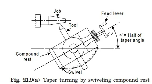
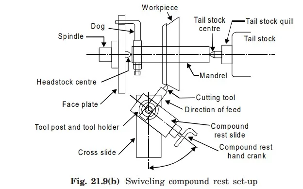
This method uses the principle of turning taper by rotating the workpiece on the lathe axis and feeding the tool at an angle to the axis of rotation of the workpiece. The tool is mounted on the compound rest which is attached to a circular base, graduated in degrees. The compound rest can easily be swiveled or rotated and clamped at any desired angle as shown in Fig. 21.9 (a). Once the compound rest is set at the desired half taper angle, rotation of the compound slide screw will cause the tool to be fed at that angle and generate a corresponding taper. This method is limited to turn a short but steep taper because of the limited movement of the cross-slide. The compound rest can be swiveled at 45° on either side of the lathe axis enabling it to turn a steep taper. The movement of the single point cutting tool in this method is being purely controlled by hand. Thus it provides a low production capacity and poor surface finish. The positioning or setting of the compound rest is accomplished by swiveling the rest at the half taper angle, if this is already known. If the diameter of the small and large end and length of taper are known, the half taper angle can be calculated. The complete setup for producing a taper by swelling the compound rest is given in Fig. 21.9(b)
Taper Turning Attachment Method
This method is commonly employed for generating external tapers only. In this method, the taper turning attachment is bolted back of the lathe machine as shown in Fig.21.10. It has guide bar which may be set at any desired angle or taper. As the carriage moves along the bed length aside over bar causes the tool to move in and out according to setting of the bar. The taper setting on the bar is duplicated on the job or work. The merit of this method is that the lathe centres are kept in alignment.

Taper Turning with Tailstock set over Method
This method is basically employed for turning small tapers on longer jobs and is confined to external tapers only. In this method, the tailstock is set over is calculated using Fig. 21.11 by loosening the nut from its centre line equal to the value obtained by formula given below.

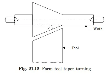
Form Tool Method
Fig. 21.12 shows this method in which a taper form is used to obtain tapers. It is limited to short external tapers. The edge tool must be exactly straight for accurate work.
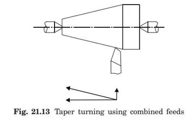
Taper Turning with Double Feeds
Taper turning can also be cut by combining the two feeds. Fig. 21.13 shows this arrangement of taper turning, which is good method of taper turning. In certain lathes both longitudinal and cross feeds may be engaged simultaneously causing the tool to follow a diagonal point which is the resultant of the magnitude of the two feeds. The direction of resultant feed may be changed by varying the rate of feeds by change gears provided inside the apron of the lathe.