The iron – carbon system, phase transformations
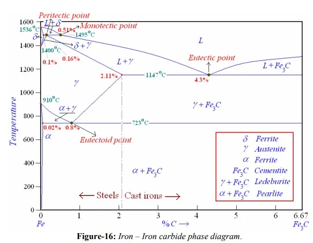
A study of iron-carbon system is useful and important in many respects. This is because (1) steels constitute greatest amount of metallic materials used by man (2) solid state transformations that occur in steels are varied and interesting. These are similar to those occur in many other systems and helps explain the properties. Iron-carbon phase diagram shown in figure-16 is not a complete diagram. Part of the diagram after 6.67 wt% C is ignored as it has little commercial significance. The 6.67%C represents the composition where an inter-metallic compound, cementite (Fe3C), with solubility limits forms. In addition, phase diagram is not true equilibrium diagram because cementite is not an equilibrium phase. However, in ordinary steels decomposition of cementite into graphite never observed because nucleation of cementite is much easier than that of graphite. Thus cementite can be treated as an equilibrium phase for practical purposes.
The Fe-Fe3C is characterized by five individual phases and four invariant reactions. Five phases that exist in the diagram are: α–ferrite (BCC) Fe-C solid solution, γ-austenite (FCC) Fe-C solid solution, δ-ferrite (BCC) Fe-C solid solution, Fe3C (iron carbide) or cementite - an inter-metallic compound and liquid Fe-C solution. Four invariant reactions that cause transformations in the system are namely eutectoid, eutectic, monotectic and peritectic.
As depicted by left axes, pure iron upon heating exhibits two allotropic changes. One involves α–ferrite of BCC crystal structure transforming to FCC austenite, γ-iron, at 910 ْC. At 1400 ْC, austenite changes to BCC phase known as δ-ferrite, which finally melts at 1536 ْC.
Carbon present in solid iron as interstitial impurity, and forms solid solution with ferrites / austenite as depicted by three single fields represented by α, γ and δ. Carbon dissolves least in α–ferrite in which maximum amount of carbon soluble is 0.02% at 723 ْC. This limited solubility is attributed to shape and size of interstitial position in BCC α–ferrite. However, carbon present greatly influences the mechanical properties of α–ferrite. α– ferrite can be used as magnetic material below 768 ْC. Solubility of carbon in γ-iron reaches its maximum, 2.11%, at a temperature of 1147 ْC. Higher solubility of carbon in austenite is attributed to FCC structure and corresponding interstitial sites. Phase transformations involving austenite plays very significant role in heat treatment of different steels. Austenite itself is non-magnetic. Carbon solubility in δ-ferrite is maximum (0.1%) at 1495 ْC. As this ferrite exists only at elevated temperatures, it is of no commercial importance. Cementite, Fe3C an inter-metallic compound forms when amount of carbon present exceeds its solubility limit at respective temperatures. Out of these four solid phases, cementite is hardest and brittle that is used in different forms to increase the strength of steels. α–ferrite, on the other hand, is softest and act as matrix of a composite material. By combining these two phases in a solution, a material’s properties can be varied over a large range.
For technological convenience, based on %C dissolved in it, a Fe-C solution is classified as: commercial pure irons with less than 0.008%C; steels having %C between 0.008- 2.11; while cast irons have carbon in the range of 2.11%-6.67%. Thus commercial pure iron is composed of exclusively α–ferrite at room temperature. Most of the steels and cast irons contain both α–ferrite and cementite. However, commercial cast irons are not simple alloys of iron and carbon as they contain large quantities of other elements such as silicon, thus better consider them as ternary alloys. The presence of Si promotes the formation of graphite instead of cementite. Thus cast irons may contain carbon in form of both graphite and cementite, while steels will have carbon only in combined from as cementite.
As shown in figure-16, and mentioned earlier, Fe-C system constitutes four invariant reactions:
v peritectic reaction at 1495 ْC and 0.16%C, δ-ferrite + L ↔ γ-iron (austenite)
v monotectic reaction 1495 ْC and 0.51%C, L ↔ L + γ-iron (austenite)
v eutectic reaction at 1147 ْC and 4.3 %C, L ↔ γ-iron + Fe3C (cementite) [ledeburite]
v eutectoid reaction at 723 ْC and 0.8%C, γ-iron ↔ α–ferrite + Fe3C (cementite) [pearlite]
Product phase of eutectic reaction is called ledeburite, while product from eutectoid reaction is called pearlite. During cooling to room temperature, ledeburite transforms into pearlite and cementite. At room temperature, thus after equilibrium cooling, Fe-C diagram consists of either α–ferrite, pearlite and/or cementite. Pearlite is actually not a single phase, but a micro-constituent having alternate thin layers of α–ferrite (~88%) and Fe3C, cementite (~12%). Steels with less than 0.8%C (mild steels up to 0.3%C, medium carbon steels with C between 0.3%-0.8% i.e. hypo-eutectoid Fe-C alloys) i.e. consists pro-eutectoid α–ferrite in addition to pearlite, while steels with carbon higher than 0.8% (high-carbon steels i.e. hyper-eutectoid Fe-C alloys) consists of pearlite and pro-eutectoid cementite. Phase transformations involving austenite i.e. processes those involve eutectoid reaction are of great importance in heat treatment of steels.
In practice, steels are almost always cooled from the austenitic region to room temperature. During the cooling upon crossing the boundary of the single phase γ-iron, first pro-eutectoid phase (either α–ferrite or cementite) forms up to eutectoid temperature. With further cooling below the eutectoid temperature, remaining austenite decomposes to eutectoid product called pearlite, mixture of thin layers of α–ferrite and cementite. Though pearlite is not a phase, nevertheless, a constituent because it has a definite appearance under the microscope and can be clearly identified in a structure composed of several constituents. The decomposition of austenite to form pearlite occurs by nucleation and growth. Nucleation, usually, occurs heterogeneously and rarely homogeneously at grain boundaries. When it is not homogeneous, nucleation of pearlite occurs both at grain boundaries and in the grains of austenite. When austenite forms pearlite at a constant temperature, the spacing between adjacent lamellae of cementite is very nearly constant. For a given colony of pearlite, all cementite plates have a common orientation in space, and it is also true for the ferrite plates. Growth of pearlite colonies occurs not only by the nucleation of additional lamellae but also through an advance at the ends of the lamellae. Pearlite growth also involves the nucleation of new colonies at the interfaces between established colonies and the parent austenite. The thickness ratio of the ferrite and cementite layers in pearlite is approximately 8 to 1. However, the absolute layer thickness depends on the temperature at which the isothermal transformation is allowed to occur.
The temperature at which austenite is transformed has a strong effect on the interlamellar spacing of pearlite. The lower the reaction temperature, the smaller will be interlamellar spacing. For example, pearlite spacing is in order of 10-3 mm when it formed at 700 ْC, while spacing is in order of 10-4 mm when formed at 600 ْC. The spacing of the pearlite lamellae has a practical significance because the hardness of the resulting structure depends upon it; the smaller the spacing, the harder the metal. The growth rate of pearlite is also a strong function of temperature. At temperatures just below the eutectoid, the growth rate increases rapidly with decreasing temperature, reaching a maximum at 600 ْC, and then decreases again at lower temperatures.
Additions of alloying elements to Fe-C system bring changes (alternations to positions of phase boundaries and shapes of fields) depends on that particular element and its concentration. Almost all alloying elements causes the eutectoid concentration to decrease, and most of the alloying elements (e.g.: Ti, Mo, Si, W, Cr) causes the eutectoid temperature to increase while some other (e.g.: Ni, Mn) reduces the eutectoid temperature. Thus alloying additions alters the relative amount of pearlite and proeutectoid phase that form.
Fe-C alloys with more than 2.11% C are called cast irons. Phase transformations in cast irons involve formation of pro-eutectic phase on crossing the liquidus. During the further cooling, liquid of eutectic composition decomposes in to mixture of austenite and cementite, known as ledeburite. On further cooling through eutectoid temperature, austenite decomposes to pearlite. The room temperature microstructure of cast irons thus consists of pearlite and cementite. Because of presence of cementite, which is hard, brittle and white in color, product is called white cast iron. However, depending on cooling rate and other alloying elements, carbon in cast iron may be present as graphite or cementite. Gray cast iron contains graphite in form of flakes. These flakes are sharp and act as stress risers. Brittleness arising because of flake shape can be avoided by producing graphite in spherical nodules, as in malleable cast iron and SG (spheroidal graphite) cast iron. Malleable cast iron is produced by heat treating white cast iron (Si < 1%) for prolonged periods at about 900 ْC and then cooling it very slowly. The cementite decomposes and temper carbon appears approximately as spherical particles. SG iron is produced by adding inoculants to molten iron. In these Si content must be about 2.5%, and no subsequent heat treatment is required.