Reverse Recovery Time
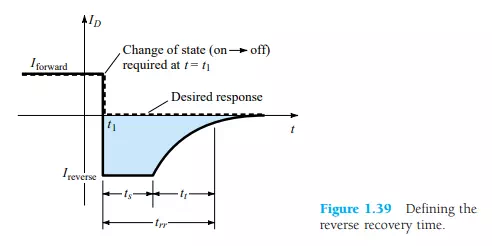
There are certain pieces of data that are normally provided on diode specification sheets provided by manufacturers. One such quantity that has not been considered yet is the reverse recovery time, denoted by trr. In the forward-bias state it was shown earlier that there are a large number of electrons from the n-type material progressing through the p-type material and a large number of holes in the n-type—a requirement for conduction. The electrons in the p-type and holes progressing through the n-type material establish a large number of minority carriers in each material. If the applied voltage should be reversed to establish a reverse-bias situation, we would ideally like to see the diode change instantaneously from the conduction state to the nonconduction state. However, because of the large number of minority carriers in each material, the diode current will simply reverse as shown in Fig. 1.39 and stay at this measurable level for the period of time ts (storage time) required for the minority carriers to return to their majority-carrier state in the opposite material. In essence, the diode will remain in the short-circuit state with a current Ireverse determined by the network parameters. Eventually, when this storage phase has passed, the current will reduce in level to that associated with the nonconduction state. This second period of time is denoted by tt (transition interval). The reverse recovery time is the sum of these two intervals: trr = ts + tt.
Naturally, it is an important consideration in highspeed switching applications. Most commercially available switching diodes have a trr in the range of a few nanoseconds to 1 s. Units are available, however, with a trr of only a few hundred picoseconds (10-12).