Globe Valves
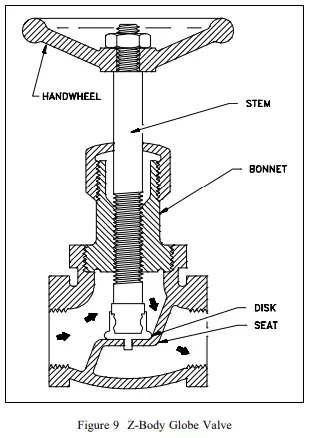
A globe valve is a linear motion valve used to stop, start, and regulate fluid flow. A Z-body globe valve is illustrated in Figure 9.
As shown in Figure 9, the globe valve disk can be totally removed from the flowpath or it can completely close the flowpath. The essential principle of globe valve operation is the perpendicular movement of the disk away from the seat. This causes the annular space between the disk and seat ring to gradually close as the valve is closed. This characteristic gives the globe valve good throttling ability, which permits its use in regulating flow. Therefore, the globe valve may be used for both stopping and starting fluid flow and for regulating flow.
When compared to a gate valve, a globe valve generally yields much less seat leakage. This is because the disk-to-seat ring contact is more at right angles, which permits the force of closing to tightly seat the disk.
Globe valves can be arranged so that the disk closes against or in the same direction of fluid flow. When the disk closes against the direction of flow, the kinetic energy of the fluid impedes closing but aids opening of the valve. When the disk closes in the same direction of flow, the kinetic energy of the fluid aids closing but impedes opening. This characteristic is preferable to other designs when quick-acting stop valves are necessary.
Globe valves also have drawbacks. The most evident shortcoming of the simple globe valve is the high head loss from two or more right angle turns of flowing fluid. Obstructions and discontinuities in the flowpath lead to head loss. In a large high pressure line, the fluid dynamic effects from pulsations, impacts, and pressure drops can damage trim, stem packing, and actuators. In addition, large valve sizes require considerable power to operate and are especially noisy in high pressure applications.
Other drawbacks of globe valves are the large openings necessary for disk assembly, heavier weight than other valves of the same flow rating, and the cantilevered mounting of the disk to the stem.
Globe Valve Body Designs
The three primary body designs for globe valves are Z-body, Y-body, and Angle.
Z-Body Design
The simplest design and most common for water applications is the Z-body. The Z-body is illustrated in Figure 9. For this body design, the Z-shaped diaphragm or partition across the globular body contains the seat. The horizontal setting of the seat allows the stem and disk to travel at right angles to the pipe axis. The stem passes through the bonnet which is attached to a large opening at the top of the valve body. This provides a symmetrical form that simplifies manufacture, installation, and repair.
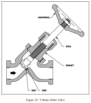
Y-Body Design
Figure 10 illustrates a typical Y-body globe valve. This design is a remedy for the high pressure drop inherent in globe valves. The seat and stem are angled at approximately 45°. The angle yields a straighter flowpath (at full opening) and provides the stem, bonnet, and packing a relatively pressure resistant envelope.
Y-body globe valves are best suited for high pressure and other severe services. In small sizes for intermittent flows, the pressure loss may not be as important as the other considerations favoring the Y-body design. Hence, the flow passage of small Y-body globe valves is not as carefully streamlined as that for larger valves.