Types of Valves
Due to the various environments, system fluids, and system conditions in which flow must be controlled, a large number of valve designs have been developed. A basic understanding of the differences between the various types of valves, and how these differences affect valve function, will help ensure the proper application of each valve type during design and the proper use of each valve type during operation.
Gate Valves
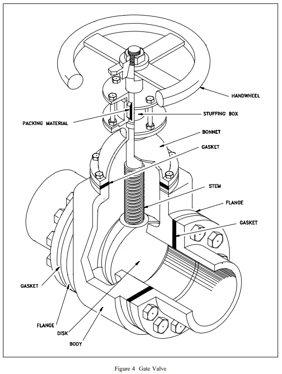
A gate valve is a linear motion valve used to start or stop fluid flow; however, it does not regulate or throttle flow. The name gate is derived from the appearance of the disk in the flow stream. Figure 4 illustrates a gate valve. The disk of a gate valve is completely removed from the flow stream when the valve is fully open. This characteristic offers virtually no resistance to flow when the valve is open. Hence, there is little pressure drop across an open gate valve. When the valve is fully closed, a disk-to-seal ring contact surface exists for 360°, and good sealing is provided. With the proper mating of a disk to the seal ring, very little or no leakage occurs across the disk when the gate valve is closed.
On opening the gate valve, the flow path is enlarged in a highly nonlinear manner with respect to percent of opening. This means that flow rate does not change evenly with stem travel. Also, a partially open gate disk tends to vibrate from the fluid flow. Most of the flow change occurs near shutoff with a relatively high fluid velocity causing disk and seat wear and eventual leakage if used to regulate flow. For these reasons, gate valves are not used to regulate or throttle flow.
A gate valve can be used for a wide variety of fluids and provides a tight seal when closed. The major disadvantages to the use of a gate valve are:
· It is not suitable for throttling applications.
· It is prone to vibration in the partially open state.
· It is more subject to seat and disk wear than a globe valve.
· Repairs, such as lapping and grinding, are generally more difficult to accomplish.
Gate Valve Disk Design
Gate valves are available with a variety of disks. Classification of gate valves is usually made by the type disk used: solid wedge, flexible wedge, split wedge, or parallel disk. Solid wedges, flexible wedges, and split wedges are used in valves having inclined seats. Parallel disks are used in valves having parallel seats. Regardless of the style of wedge or disk used, the disk is usually replaceable. In services where solids or high velocity may cause rapid erosion of the seat or disk, these components should have a high surface hardness and should have replacement seats as well as disks. If the seats are not replaceable, seat damage requires removal of the valve from the line for refacing of the seat, or refacing of the seat in place. Valves being used in corrosion service should normally be specified with replaceable seats.
Solid Wedge
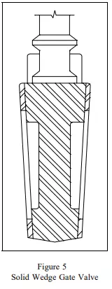
The solid wedge gate valve shown in Figure 5 is the most commonly used disk because of its simplicity and strength. A valve with this type of wedge may be installed in any position and it is suitable for almost all fluids. It is practical for turbulent flow.
Flexible Wedge
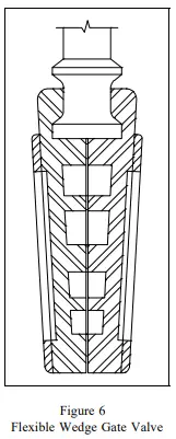
The flexible wedge gate valve illustrated in Figure 6 is a one-piece disk with a cut around the perimeter to improve the ability to match error or change in the angle between the seats. The cut varies in size, shape, and depth. A shallow, narrow cut gives little flexibility but retains strength. A deeper and wider cut, or cast-in recess, leaves little material at the center, which allows more flexibility but compromises strength.
A correct profile of the disk half in the flexible wedge design can give uniform deflection properties at the disk edge, so that the wedging force applied in seating will force the disk seating surface uniformly and tightly against the seat.
Gate valves used in steam systems have flexible wedges. The reason for using a flexible gate is to prevent binding of the gate within the valve when the valve is in the closed position. When steam lines are heated, they expand and cause some distortion of valve bodies. If a solid gate fits snugly between the seat of a valve in a cold steam system, when the system is heated and pipes elongate, the seats will compress against the gate and clamp the valve shut. This problem is overcome by using a flexible gate, whose design allows the gate to flex as the valve seat compresses it.
The major problem associated with flexible gates is that water tends to collect in the body neck. Under certain conditions, the admission of steam may cause the valve body neck to rupture, the bonnet to lift off, or the seat ring to collapse. Following correct warming procedures prevent these problems.
Split Wedge
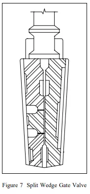
Split wedge gate valves, as shown in Figure 7, are of the ball and socket design. These are self-adjusting and selfaligning to both seating surfaces. The disk is free to adjust itself to the seating surface if one-half of the disk is slightly out of alignment because of foreign matter lodged between the disk half and the seat ring. This type of wedge is suitable for handling noncondensing gases and liquids at normal temperatures, particularly corrosive liquids. Freedom of movement of the disk in the carrier prevents binding even though the valve may have been closed when hot and later contracted due to cooling. This type of valve should be installed with the stem in the vertical position.
Parallel Disk
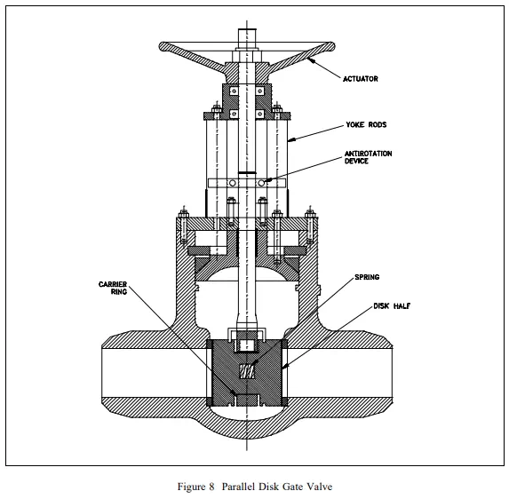
The parallel disk gate valve illustrated in Figure 8 is designed to prevent valve binding due to thermal transients. This design is used in both low and high pressure applications. The wedge surfaces between the parallel face disk halves are caused to press together under stem thrust and spread apart the disks to seal against the seats. The tapered wedges may be part of the disk halves or they may be separate elements. The lower wedge may bottom out on a rib at the valve bottom so that the stem can develop seating force. In one version, the wedge contact surfaces are curved to keep the point of contact close to the optimum. In other parallel disk gates, the two halves do not move apart under wedge action. Instead, the upstream pressure holds the downstream disk against the seat. A carrier ring lifts the disks, and a spring or springs hold the disks apart and seated when there is no upstream pressure.
Another parallel gate disk design provides for sealing only one port. In these designs, the high pressure side pushes the disk open (relieving the disk) on the high pressure side, but forces the disk closed on the low pressure side. With such designs, the amount of seat leakage tends to decrease as differential pressure across the seat increases. These valves will usually have a flow direction marking which will show which side is the high pressure (relieving) side. Care should be taken to ensure that these valves are not installed backwards in the system.
Some parallel disk gate valves used in high pressure systems are made with an integral bonnet vent and bypass line. A three-way valve is used to position the line to bypass in order to equalize pressure across the disks prior to opening. When the gate valve is closed, the three-way valve is positioned to vent the bonnet to one side or the other. This prevents moisture from accumulating in the bonnet. The three-way valve is positioned to the high pressure side of the gate valve when closed to ensure that flow does not bypass the isolation valve. The high pressure acts against spring compression and forces one gate off of its seat. The three-way valve vents this flow back to the pressure source.