DIODE TESTING
The condition of a semiconductor diode can be determined quickly using (1) a digital display meter (DDM) with a diode checking function, (2) the ohmmeter section of a multimeter, or (3) a curve tracer.
Diode Checking Function
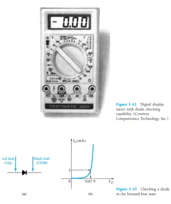
A digital display meter with a diode checking capability appears in Fig. 1.42. Note the small diode symbol as the bottom option of the rotating dial. When set in this position and hooked up as shown in Fig. 1.43a, the diode should be in the “on” state and the display will provide an indication of the forward-bias voltage such as 0.67 V (for Si). The meter has an internal constant current source (about 2 mA) that will define the voltage level as indicated in Fig. 1.43b. An OL indication with the hookup of Fig. 1.43a reveals an open (defective) diode. If the leads are reversed, an OL indication should result due to the expected open-circuit equivalence for the diode. In general, therefore, an OL indication in both directions is an indication of an open or defective diode.
Ohmmeter Testing
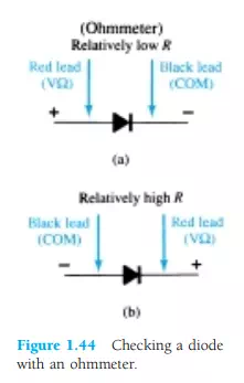
The forward-bias resistance of a semiconductor diode is quite low compared to the reverse-bias level. Therefore, if we measure the resistance of a diode using the connections indicated in Fig. 1.44a, we can expect a relatively low level. The resulting ohmmeter indication will be a function of the current established through the diode by the internal battery (often 1.5 V) of the ohmmeter circuit. The higher the current, the less the resistance level. For the reverse-bias situation the reading should be quite high, requiring a high resistance scale on the meter, as indicated in Fig. 1.44b. A high resistance reading in both directions obviously indicates an open (defective device) condition, while a very low resistance reading in both directions will probably indicate a shorted device.