|
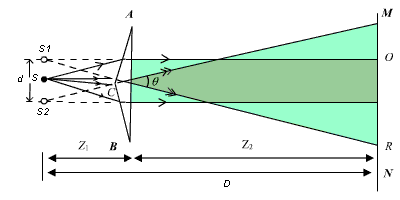
A Fresnel Biprism is a thin
double prism placed base to base and have very small refracting angle ( 0.5o).
This is equivalent to a single prism with one of its angle nearly 179° and
other two of 0.5o each.
The interference is observed
by the division of wave front. Monochromatic light through a narrow
slit S falls on biprism , which divides it into two
components. One of these component is refracted from upper portion of
biprism and appears to come from S1 where the other one refracted
through lower portion and appears to come from S2. Thus S1 and S2 act
as two virtual coherent sources formed from the original source. Light waves
arising from S1and S2 interfere in the shaded region and
interference fringes are formed which can be observed on the screen .
Applications of
Fresnel's Biprism
Fesnel biprism can be used to
determine the wavelength of a light source (monochromatic), thickness of a
thin transparent sheet/ thin film, refractive index of medium etc.
A.
Determination of wave length of light
As expression for fringe
width is 
Biprism can be used to
determine the wavelength of given monochromatic light using the expression.

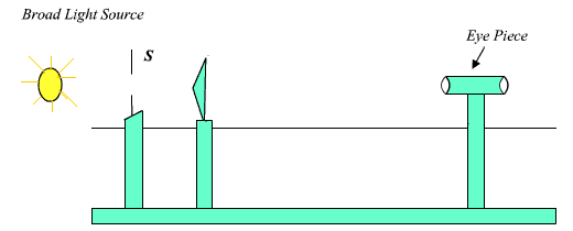
Experimental
Arrangement. Light
from monochromatic source is made to fall on a thin slit mounted vertically
on a rigid optical bench fitted with a scale. The biprism and the screen (in
this case an eye piece) are also mounted vertically. The eye piece can be
moved in the plane perpendicular to the axis of bench using a micrometer
based translation stage.
(i) Measurement of fringe
width: To get β, fringes are first observed in the
field of view of the microscope. The vertical wire of the eyepiece is made to
coincide with one of the fringes and screw of micrometer is moved sideways
and number of fringes is counted.
β =Distance moved /
number of fringes
passed
…( 5)
(ii)
Measurement of D: This distance between source and
eyepiece is directly measured on the optical bench scale.
(iii) Determination
of d: To determine the separation between the two virtual
sources ( d ), a convex lens of short focal length is introduced
between the biprism and the eye piece, keeping the distance between the slit
and eyepiece to be more than four times the focal length of lens. The lens is
moved along the length of bench to a position where two images of slits are
seen in the plane of cross wires of eye piece. The distance between these two
images of slit is measured by setting the vertical cross wire successively on
each of images and recording the two positions of cross wire using
micrometer. Let this separation be d1 . Now the lens is moved such
that for another position of lens, again two images of slit are seen on eye
piece. Let d2 be the separation between these two images.
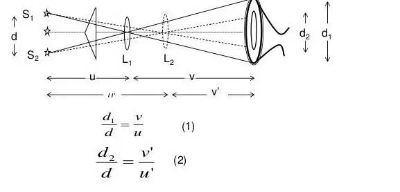
Since these two positions of
lens are conjugate, the separation between the virtual source ‘d ' is
given by using 1 and 2 as

where d1 and d2 are the
distance between S1 and S2 for two position of lens.
B Determination of thickness
of a thin film:
To determine the thickness of
transparent thin sheet (mica), the monochromatic source is replaced by white
light source.
The position of this central
white fringe is recorded by focusing the cross wire of eye piece on it and
taking this reading of micrometer scale. Now mica sheet is introduced in the
path of one wave. (such that it blocks the one half of biprism). By doing it
the one wave traverse an extra optical path and the path difference between
the two waves is not same and entire fringe pattern shifts. The central white
fringe is now shifted to another position of cross wire. If ‘S' is the shift
in position of white fringe and  be
the refractive index of mica sheet, thickness ‘t' of mica sheet is given
by be
the refractive index of mica sheet, thickness ‘t' of mica sheet is given
by
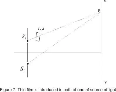
Time required by light to reach from S1 to point P

where v=c/μ
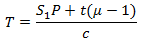
Hence equivalent path that is covered by light in air is S1P+t(μ-1)
Optical path difference at P
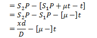
Therefore nth fringe shift is given by
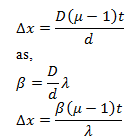
where λ is the wavelength of the wave;  is displacement
of fringes and is displacement
of fringes and  is
fringe width is
fringe width
|