Thermocouple Validation and Testing
Thermocouples are non-adjustable measuring devices, so we cannot calibrate them. However, we can validate functioning for a range of temperature through using a thermocouple calibration bath.
Thermocouple calibration procedure.
The thermocouple validation procedure is widely used for all furnaces and also in heating equipment. Thermocouples are non-adjustable measuring devices, so we cannot calibrate them. However, we can validate functioning for a range of temperature through using a thermocouple calibration bath.
Thermocouple Calibration Procedure
Generally we use a temperature controller or SCADA to indicate thermocouple temperature. To validate thermocouple temperature on the display, we measure mV at the thermocouple end and by using standard ASTM E230-03 (Standard Specification and Temperature-Electromotive Force (EMF) Tables for Standardized Thermocouples") we can obtain Temperature in degrees Centrigrade at a particular furnace location. We want to ensure that the same temperature will be displayed on SCADA or indicator and deviation, if any, will be recorded accordingly.
Thermocouple Basics
Thermocouples are broadly used temperature measuring instruments found in most furnaces, kilns, powerplants, and various industries. In 1821, Mr. Thomas J. Seebeck discovered that a thermocouple would generate a current in a closed circuit when one junction is at a different temperature from another. Thermocouples contains two dissimilar metals and when coupled at one end ("hot" junction ) and at other end ("cold" junction ), generate a unique microvoltage at a particular temperature.
The temperature indicator, or thermomete,r can convert this mV into degrees Centrigrade, resulting in a direct temperature reading on the indicator. This temperature reading can be transferred via remote controller, PLC, or SCADA to display in the operator control room located in another place. PID or PLC controls furnace temperature with taking feedback from thermocouple.
Thermocouple Types
To deal with different specific ranges of temperature, a variety of metals are used in the manufacturing of themocouples. There are eight types of thermocouples generally used in the industries considering characteristics of the material. Each type is denoted by a letter. Please click the following link to view a chart.
Type ![]()
Type of Thermocouple ~Material ~Temperature Range ( °C )
Noble Metal
S type ~Pt -10% Rh Vs Pt ~0 to 1450
R type ~Pt -13% Rh Vs Pt ~0 to 1450
B type ~Pt -30% Rh Vs Pt -6% Rh ~0 to 1750
Base Metal
E type ~Ni -10% Cr Vs Constantan ~0 to 1000
J type ~Fe Vs Constantan ~0 to 760
K type ~Ni -10% Cr Vs Ni-5% ( Al, Si ) ~0 to 1150
N type ~Ni -14% Cr -1.5% Si Vs Ni -4.5% Si -0.1%Mg ~0 to 1150
T type ~Cu Vs Constantan ~0 to 400
Read like: Type S thermocouple is manufactured using a platinum/10% rhodium for positive arm and pure platinum for negative arm.
Thermocouple Calibration
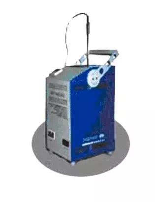
The thermocouple calibration procedure involves the measuring of thermocouple emf (in mV) at a specified temperature range with the help of a thermocouple bath. The thermocouple calibration bath contains a valid temperature controller and a master thermocouple to compare temperature. The subject thermocouple is inserted in the bath and should be insulated properly. The temperature reading is recorded at different points and compared with the mV produced by the thermocouple placed for calibration.
Any difference between the readings taken from the thermocouple calibration bath controller and from the mV-originated temperature shall be noted for finding the error. During this procedure, the surrounding environment temperature and humidity should be considered accordingly.
This activity is carried out in a laboratory, therefore the subject thermocouple needs to be disconnected from the furnace and carried to the laboratory to be tested with the calibration bath. This results in no functioning of the particular furnace zone during the calibration process, so it is wise to have a spare themocouple.
If thermocouple verification is desired before the calibration frequency time, it is possible to validate thermocouple operation on the furnace itself. On-site validation involves placing another thermocouple near (75 mm or less) the unit to be tested and recording the readings of each simultaneously. This is called a system accuracy test.
Analysis
The direct comparison method between thermocouple and display is not truthful because it is not linking any internal error (offset) of the thermocouple, test instrument, PLC and SCADA or recorder.
The following steps shall be taken to validate thermocouple temperature displayed on SCADA or recorder.
1. Measurement of thermocouple mV and addition of thermocouple error (correction factor).
2. Addition of measuring instrument error (internal bias) by which reading is taken.
3. Addition of PLC offset or SCADA (recorder) offset.
4. The addition of all these error readings with the measured temperature reading will be the correct temperature reading shown on the screen.
Therefore:
Temperature readings displayed on SCADA or Controller= Readings measured on thermocouple by indicator in Deg Centigrade + Indicator error + Thermocouple error + PLC offset + SCADA or Controller offset.