What Is Cogging In Electrical Motors?
The design of an AC electrical motor is basically such that it has two parts – the outer fixed stator having armature coil to which alternating current is supplied, while a freely rotating rotor inside having permanent magnets. On the whole this arrangement gives rise to varying flux which leads to motor rotation.
Yet it may happen sometimes that when the current is applied the motor refuses to start or run despite the fact that there is no load on the shaft externally, nor is there any mechanical jam such as bearing fault or something. So what exactly does cause this type of a situation to occur? We will try to find the reason behind such behaviour and this is also known as magnetic locking or cogging of electrical motors. Another popular term used for this phenomenon is also known as teeth locking, the reason for which you will know as you study about the phenomenon of electrical motor cogging in the sections below.
Reasons for Cogging
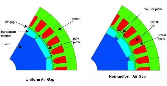
First of all just take a look at the diagram below which shows the typical construction of such a motor and the image clearly shows the various elements such as pole pitch, air gap and so forth.
When the number of stator teeth is equal to the number of rotor teeth, a situation may occur wherein the teeth of one of the elements are directly in front of each other. In this geometric position the reluctance to the magnetic path is minimal; as compared to the other relative positions of the stator and rotor. We know that in this universe every process tries to take the path of least resistance, hence the motor tends to get stuck at this position refusing to budge despite the fact that no external load or force is holding it back.
There are several ways to overcome this sort of a situation. The actual solution may vary with the design and purpose of the motor and is best left to the people involved in the actual design. Some of these possible solutions could be as follows.
· The number of rotor slots are made prime vis-à-vis the number of stator slots.
· Skewing of the stator stack
· Skewing of the magnetic poles.
Normally such arrangements do add somewhat to the manufacturing cost as it adds complexity to the process. For example if the magnetic pole has to be skewed it requires special constructional requirements.
Similarly if the stator is made skew, it could results in problems with winding of coils and also leads to secondary problems such as reduction of effective slot area and increased stator resistance. However this in turn leads to lowered cogging probability.
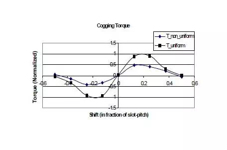
Given below is a diagram which shows the difference between uniform and non-uniform air gap construction. It also shows the magnitude of cogging torque in these two cases in the form of a graph for the aid of the reader, and you can quickly make out the difference at a glance.