Phase Comparison
Phase comparison relay systems monitor the current direction at each line terminal of the protected line and transmit this information to the other terminal via a communication channel.
Each line terminal compares local and remote current direction and trips if the current is into the line from both terminals. The communication channel is normally an on/off type of communications, transmitting only when the overcurrent detector’s thresholds have been exceeded.
This system is immune to tripping on overloads or system swings since it operates on current direction only. It needs no potential source unless it has to be supervised by distance relays because of low fault currents.
Current or distance fault detectors are used to supervise tripping. These detectors have to be set above line charging current, which can appear to the relays as an internal fault at low loads. Internal timers have to be set to compensate for the transit time of the communication channel.
One of the most popular applications of this system is on lines with series capacitorsbecause it is less likely that such a current-operated scheme will operate incorrectly for faults near the capacitors.
Pilot Wire
This scheme is a form of phase comparison since it compares current direction at each terminal. The difference between this scheme and others is that a pair of telephone wires is used as the communication channel.
A special filter in the relay converts the three-phase currents to a single-phase voltage and applies this voltage to the wires. When current flows through the protected section, the voltages at each end oppose each other and no current flows in the operate coils.
When current enters the line from each end, the voltage on the pilot wire reverses to allow current to circulate through the operate coils and consequently trip both ends.
Special monitor relays sound an alarm if the pilot wire pair becomes open or shorted. The wire line has to have adequate protection against induced voltages and a rise in station ground potential but may not use carbon block protectors because the line has to remain in service while the protection is operating.
Neutralizing transformers and gas tubes with mutual drainage reactors, all with adequate voltage ratings, comprise the preferred pilot wire protection package.
This relaying has the advantage of simplicity and does not require a potential source. It does not provide backup protection.
Its application is limited to short lines a mile or so in length because of pilot wire cost and increased exposure. The system’s dependability is based on the integrity of the pilot wires themselves.
Many pilot wire systems have been replaced with other pilot schemes because of the failure of the pilot wire system to function reliably and securely.
Recently, pilot wire systems have been replaced with fiber-optic systems providing the communications systems, using a module to convert the output voltage to a light signal. These modified systems have provided a more dependable and secure protection system.
Single-Phase Comparison
This scheme applies a sequencing network to the current inputs to the relay to produce a single-phase voltage output. This output is proportional to the positive, negative, and zero phase sequence components of the input currents.
This signal is squared so that the positive portion of the signal provides the positive portion of the square wave.
The negative portion of the signal provides the zero portion of the square wave. Two fault detectors are normally used to provide security, with the more sensitive detector used as the carrier start to transmit the signal to the remote end. The less sensitive detector is used to arm the comparison module for a trip upon the correct comparison of the local and remote signals.
See Figure 5.
Normally current-operated units are used as the fault detectors. In a case where the fault current is less than the load current, impedance-operated units may be used for fault detection.
The use of impedance fault detectors will increase the cost of the system because of the necessity of having line potentials for the operation of the relay.
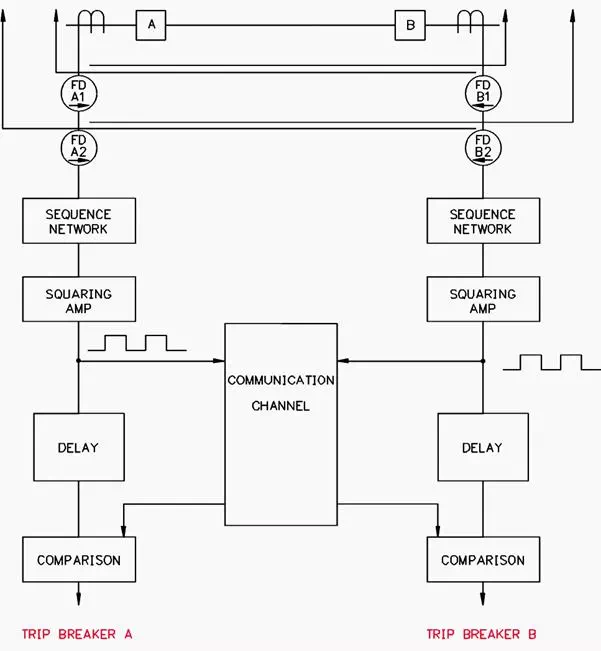 Figure 5 – Single-Phase Comparison Scheme
Dual-Phase Comparisn
This scheme is similar to the single-phase comparison scheme except that square wave signals are developed for the positive and the negative portions of the single-phase voltage output of the sequencing network. Each signal requires a separate channel for the transmission of information to the remote site.
This scheme can provide a slightly higher speed of detection since faults are detected on both the positive and the negative portions of the single-phase voltage output of the sequencing network.
This scheme is normally used with a frequency-shift channel, which is continuously transmitted. On a power line carrier it is configured as an unblocking scheme.
Segregated Phase Comparison
This scheme is similar to the single-phase comparison scheme except that a square wave is developed for each phase of the transmission line. A communication channel is required for each phase to provide communications to the remote terminal.
Comparisons are made on each of the three phases. The operation of the scheme is basically as described above in the previous phase comparison schemes.