Pilot schemes for transmission line protection
When do we use pilot schemes?
Pilot schemes simultaneously measure and monitor system parameters at all terminals of a transmission line, local and remote, and then respond according to their predetermined functions. These schemes require the use of a communications channel that may be provided through pilot wires, microwave, fiber, or power line carrier.
 Pilot schemes for transmission line protection (photo credit:
Siemens)
Pilot schemes for transmission line protection (photo credit:
Siemens)
If the measured parameters exceed threshold values, appropriate actions are initiated.
Pilot schemes can generally be broken into two primary categories. Those categories are directional comparison and phase comparison. Directional schemes use directional distance relays for phase fault detection and either directional distance relays or directional overcurrent relays for ground fault detection.
The decision to trip is based on relay setting thresholds being exceeded and the faults being located in the predetermined direction for trip.
Phase comparison schemes are an extension of the differential protection principal. Currents from all line terminals are converted into a composite signal, transmitted to the remote terminals, and compared to the local terminal composite signal. The result of the comparison will result in a trip if the relay setting threshold is exceeded.
Phase comparison schemes are inherently directional and secure, not tripping for faults outside the protected zone of protection.
Directional Comparison
Directional comparison schemes are divided into four categories:
Blocking Schemes
Directional comparison blocking uses distance relays as directional indicators and block initiation for phase faults. Either distance or directional overcurrent relays may be used for ground fault indicators and block initiation.
Each terminal has trip and start relays. The trip relay reaches toward the remote terminal and a little beyond. The start relay reaches backwards, away from the protected section. The trip relay attempts tripping when it operates unless it is stopped by receipt of a blocking signal (carrier, audio tone, or microwave) from the remote end. The start relays at each end initiate the blocking signal.
Thus, if only the trip relays see the fault, it is within the protected section and both ends trip. If the fault is just outside one end, the start relays at that end operate and send a block signal to the remote end, which would otherwise trip. The ground relays operate similarly.
A tripping delay is necessary to allow for the receipt of the blocking signal. A typical delay time of 6 to 16 msec is used to coordinate for the channel delay in communications.
The communication channel is not required for tripping the breakers since the breakers will trip in the absence of the blocking signal. Failure of the channel could result in overtripping of the breakers for adjacent line faults within the reach setting of the distance relays.
Blocking directional comparison is commonly used with on/off type carrier facilities. Since it is not necessary to drive a signal through a fault to operate this scheme, it is the most popular carrier relaying system. See Figure 1.
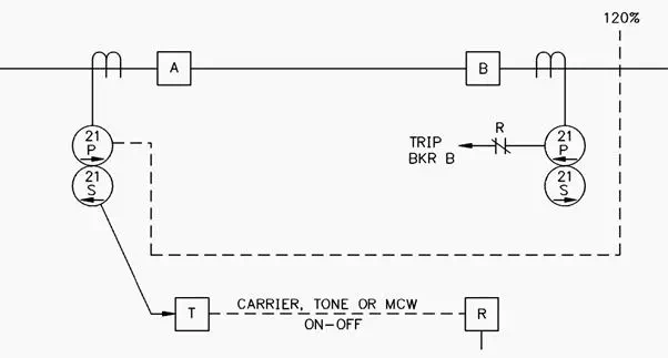 Figure 1 – Blocking Directional Comparison
Unblocking Schemes
Directional comparison unblocking is similar to the blocking scheme except that the start relays are deleted and the blocking, “guard” signal is sent continuously. See Figure 2.
The communication signal for an unblocking scheme uses a frequency shift keying (FSK) channel.
For an internal fault, the frequency is shifted to the unblock, “trip” frequency. The receivers receive the trip frequency and close the output contact, which in series with the 21P relay output contact will trip the breaker.
For an external fault, within the reach of one of the 21P relays, the distant 21P relay will see the fault while the local 21P relay will not see the fault since it is behind the relay.
The distant 21P relay will shift its transmitter frequency to trip.
The local 21P relay will not send the trip frequency or close the 21P output contacts. The line thus stays in service. Should the receivers fail to receive a guard signal and a trip signal, the receivers will allow typically 150 msec of receiver contact closure to permit the 21P relay contact to trip the line.
After this time limit, the communication channel will lock out.
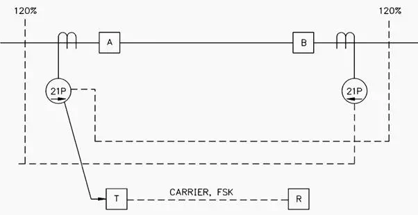 Figure 2 – Directional Comparison Unblocking
This scheme is more secure since overtripping is avoided at all times with the exception of the 150-msec interval during the loss of signal. Reliability is improved since the communication channel operates continuously and can be monitored, providing an alarm in the case of failure.
The scheme is applicable for two-terminal and multi-terminal lines. Separate channels are required between each pair of line terminals.
Overreaching Transfer Trip Schemes
Permissive overreach is also a simple scheme, requiring only one overreaching fault detector at each terminal. This fault detector sends both a trip signal and attempts local tripping through a contact on the receiver.
If both relays see a fault, both ends trip simultaneously.
The scheme appears similar to the directional comparison unblocking scheme of Figure 2. A trip signal is required for this scheme to trip. Power line carrier channels therefore are not recommended for these schemes since a fault could short out the carrier signal.
These channels are normally used with audio tones with frequency shift keying over microwave, leased line, or fiber-optic communications.
The overreaching transfer trip scheme provides highly secure transmission line protection since a trip signal is required from both ends of the line for tripping to occur. The dependability of the scheme may be less than the blocking schemes since the trip signal has to be received before the tripping is initiated.
The scheme is often used when an existing non-piloted scheme has communications added for piloting.