Breaker-and-a-Half
The breaker-and-a-half configuration consists of two main buses, each normally energized. Electrically connected between the buses are three circuit breakers and, between each two breakers, a circuit as diagrammed in Figure 7.
In this arrangement, three circuit breakers are used for two independent circuits; hence, each circuit shares the common center circuit breaker, so there are one-and-a-half circuit breakers per circuit.
The breaker-and-a-half configuration provides for circuit breaker maintenance, since any breaker can be removed from service without interrupting any circuits.
Additionally, faults on either of the main buses cause no circuit interruptions. Failure of a circuit breaker results in the loss of two circuits if a common breaker fails and only one circuit if an outside breaker fails.
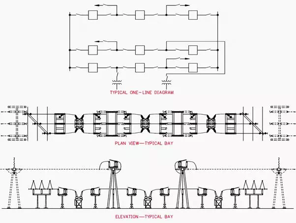 Figure 7 – Breaker-and-a-Half Configuration
A typical bus configuration for a breaker-and-a-half arrangement is shown in Figure 7. This is the same basic equipment assemblage as described for the ring bus scheme.
Frequently, substations are initially constructed with a ring bus arrangement and ultimately expanded into a breaker-and-a-half configuration to obtain the additional flexibility and reliability required with the additional circuits.
Bay centerline spacing should be carefully planned to permit equipment maintenance and removal.
Advantages
· Flexible operation.
· High reliability.
· Can isolate either main bus for maintenance without disrupting service.
· Can isolate any circuit breaker for maintenance without disrupting service.
· Double feed to each circuit.
· Bus fault does not interrupt service to any circuits.
· All switching done with circuit breakers.
Disadvantages
· One-and-a-half breakers are required per circuit.
· Relaying is involved, since the center breaker has to respond to faults of either of its associated circuits.
· Each circuit should have its own potential source for relaying.