Main and Transfer Bus
A main and transfer bus configuration consists of two independent buses, one of which, the main bus, is normally energized. Under normal operating conditions, all incoming and outgoing circuits are fed from the main bus through their associated circuit breakers and switches.
If it becomes necessary to remove a circuit breaker from service for maintenance or repairs, the integrity of circuit operation can be maintained through use of the bypass and bus tie equipment.
The bypass switch for the circuit breaker to be isolated is closed, the bus tie breaker and its isolation switches are closed, and the bypassed breaker and its isolation switches are opened to remove the breaker from service. The circuit is then protected by the bus tie breaker.
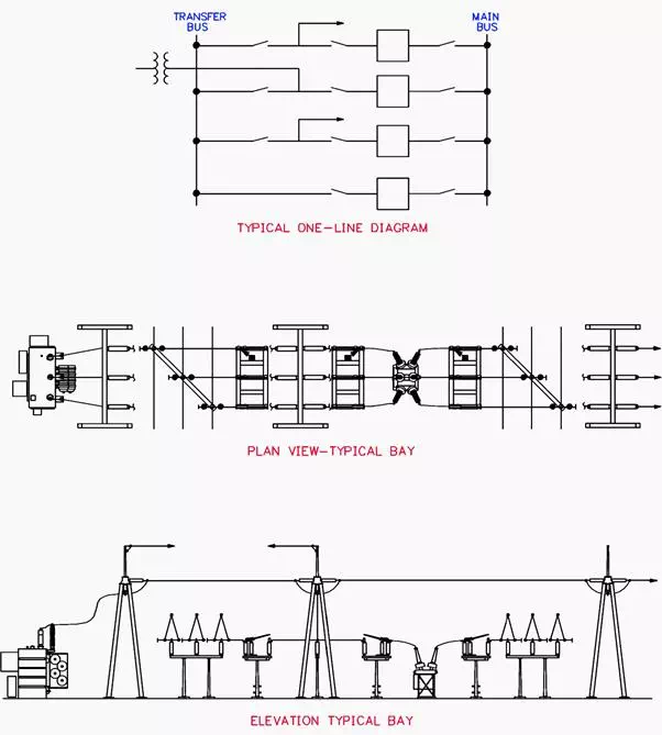 Figure 4 – Main and Transfer Bus – Low Profile Configuration
Figure 4 illustrates a main and transfer bus configuration in a low-profile arrangement. For comparison, Figure 5 shows the same switching scheme with high-profile box-type structures.
With the box-type structure arrangement, two circuit positions can be accommodated per equipment bay.
However, with the low-profile arrangement, each circuit requires its own bay and, as a result, somewhat more land area may be required. When the low-profile configuration is used, equipment bays should be limited in width to a maximum of two bays before the bay-to-bay centerline spacing is increased to accommodate circuit breaker maintenance and removal.
Without the additional space, these tasks can become very difficult.
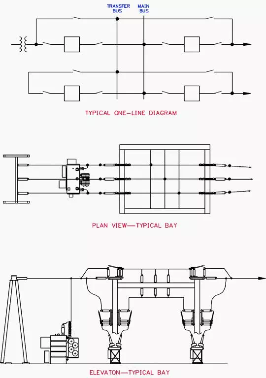 Figure 5 – Main and Transfer Bus – High Profile Configuration
The high-profile, box-type structure arrangement shown in Figure 5 can accommodate multiple circuits in a relatively small area. The configuration is particularly suitable in environmentally shielded or otherwise isolated locations, where only a limited substation site is available.
This arrangement is generally limited to distribution and subtransmission voltage levels. At transmission voltage levels, independent structures and strain bus interconnections can be used.
Advantages
· Accommodation of circuit breaker maintenance while maintaining service and line protection.
· Reasonable in cost.
· Fairly small land area.
· Easily expandable.
Disadvantages
· An additional circuit breaker is required for bus tie.
· Since the bus tie breaker, have to be able to be substituted for any line breaker, its associated relaying may be somewhat complicated.
· Failure of a circuit breaker or a bus fault causes loss of the entire substation.
· Somewhat complicated switching is required to remove a circuit breaker from service for maintenance.