Control house layout -1
Control and Relay protection Panels
Most protection relaying, metering, and control equipment is mounted on fabricated control and relay panels installed within the control house. A variety of panel types is available to suit individual requirements.
Figures 4, 5 and 6 show examples of various panel layouts.
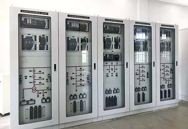 Figure 4 – Control and protection panels
Single vertical panels can be used, particularly for distribution circuits where space requirements are minimal. The relaying, metering, and control equipment can all be mounted on one panel, allocating a separate panel for each circuit. In some instances, two circuits may share the same panel.
Double or duplex panels are commonly used for higher voltage circuits, necessitating additional space for equipment mounting. Normally, these panels are arranged in two parallel rows with the panel backs facing each other. In this configuration, operating, instrumentation, and control equipment for a circuit is installed on the front of one panel, and the corresponding relaying equipment for the same circuit is installed on the front of the panel directly to the rear.
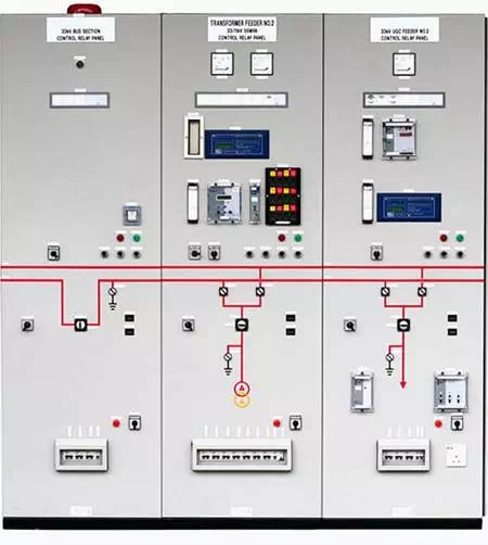 Figure 5 – Protection relay panel (photo credit: pestech.com.my)
In some instances, two circuits may share the same control and relaying panels.
Some equipment such as static relaying systems and communications equipment is available mounted in racks. Consequently, separate relay and/or control panels are not required for this equipment.
Modern SCADA and substation automation schemes may require space for installation of a PC with monitor and keyboard, as well as programmable logic controllers and data highway interface modules. This equipment can often be rack-mounted or installed in control panels, as appropriate.
The trend is toward more compact equipment arrangements that often reduce overall control house size.
Individual three-phase microprocessor relays can replace three single-phase electromechanical relays and associated voltage, current, and power meters, all in one case.
Compact relay and programmable logic controller designs can be mounted on 48.26-cm (19-inch) racks.
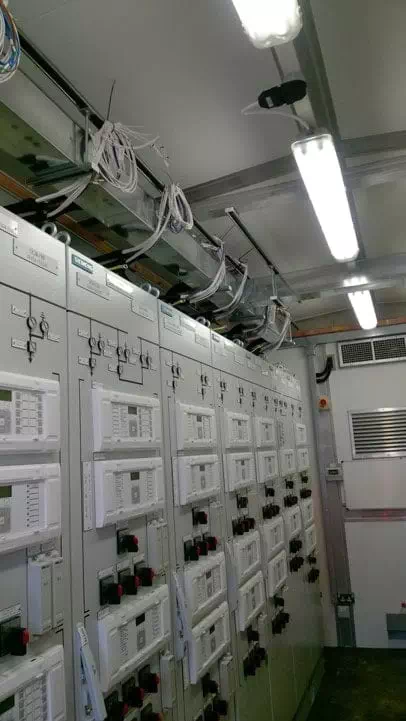 Figure 6 – Relay protection panels in control room (photo credit:
Protection Installation Services Ltd)
Figure 6 – Relay protection panels in control room (photo credit:
Protection Installation Services Ltd)
To facilitate operation, panels are located in an arrangement that conforms as closely as possible to the actual equipment and circuit layout in the substation yard. To assist in circuit location and operation, mimic buses are sometimes used on the control panels, particularly for large complex substations.
The mimic buses identify the bus and circuit arrangements.
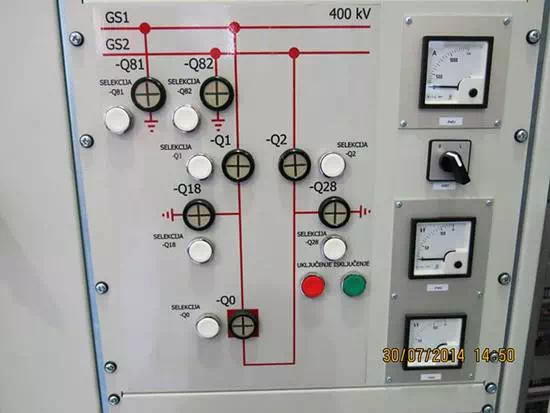 Figure 7 – Mimic diagram in protection relay panel (photo credit:
Edvard Csanyi)
Figure 7 – Mimic diagram in protection relay panel (photo credit:
Edvard Csanyi)
Mimic buses may be implemented on screens viewed from a PC monitor. When practical, position meters at eye level and switches at a convenient operating level. Locate recording meters for ease of viewing and chart replacement.
Locate relays beginning at the tops of the relay panels and working downward. Relays with glass covers should not be located within 12 inches of the floor to avoid inadvertent breaking of the glass. Locate operating switches at convenient heights near the center of the boards. Require nameplates for all devices.
Provide ample space for relay installation, removal, operation, and testing. Panel construction can include removable front plates for device mounting.
Panels may also include 19-inch rack mounting facilities. Many of the newer relays and items of accessory equipment are designed to fit into 19-inch racks. Cover plates may cover space reserved for future use. In this way, only a new predrilled plate is required when changing out a device or modifying the configuration.
Cutting, drilling, or covering openings in the panels is eliminated.
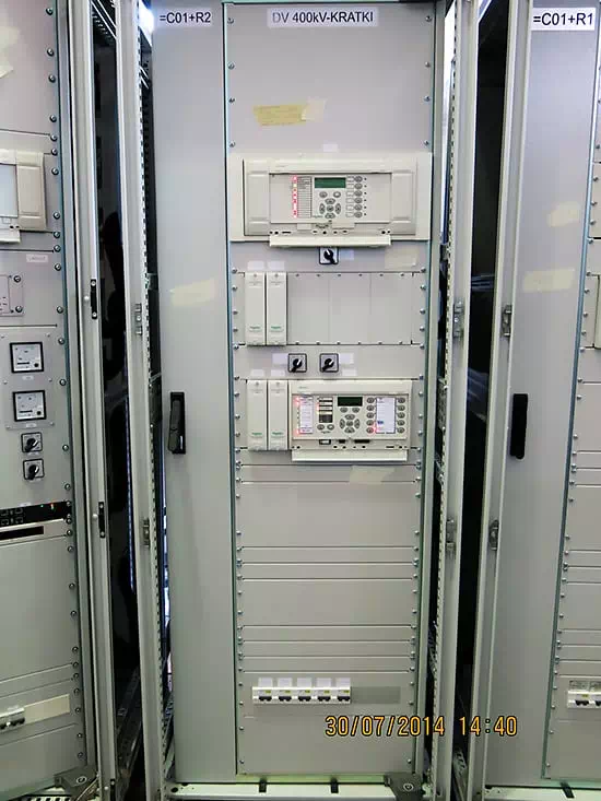 Figure 8 – 19-inch rack-mounted protection relay type MICOM and
test sockets (photo credit: Edvard Csanyi)
Figure 8 – 19-inch rack-mounted protection relay type MICOM and
test sockets (photo credit: Edvard Csanyi)
Panel wiring is accomplished on the backs of the panels. Devices are interconnected and wired to terminal blocks, as required, for operation and connection to devices on other panels.
Panels can include small sections perpendicular to the main section at each end for installation of terminal blocks, fuse blocks, or small auxiliary devices.
Cable connections from the equipment in the substation yard can be made directly to terminal blocks mounted on the panels or to strategically placed terminal cabinets. Interconnections between the terminal cabinets and the panels can then be made with single conductor wire.
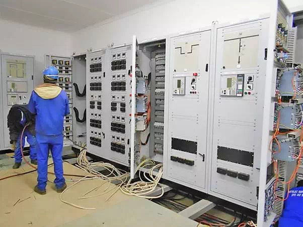 Figure 9 – Cabling of relay protection panels
Anchor panels to the floor in such a way as to facilitate relocation to coincide with yard equipment and circuit relocations.
Panel arrangement in the control house should permit ready accessibility to the backs of the panels. Some vendors of pre-engineered buildings can provide completely wired and tested control and relay panels and auxiliary AC/DC power systems as part of the building package.
In this case, custom-designed relay and control schematics are submitted to the building vendor. The building vendor fabricates the panels, provides the relays and controls, wires the panels, and tests the complete installation.
In this way, the entire panel line-up can be witness-tested in the factory. The complete building system is shipped to the site, fully tested. Only the external wiring from the building to the outdoor equipment has to be field-installed.