Common bus configurations in substations up to 345 kV
Comparison of bus configurations
This technical article explains six most common bus configurations used for distribution, transmission, or switching substations at voltages up to 345 kV. Presented single line diagrams and layouts are generalized since they depend on the type and voltage(s) of the substations.
The physical size, type, and arrangement of major equipment, such as power transformers, power circuit breakers, and switches, may cause variance in the layouts to suit individual requirements.
Parts of different configurations may be combined, as required, to achieve desired configurations. That leads to the huge number of possible substation configurations.
It is important that the engineer’s plans remain as flexible as possible during substation layout to allow for unforeseen difficulties as designs progress. Coordinate activities with the equipment manufacturers to ensure that each design detail reflects the actual equipment to be used.
Single Bus
A single bus configuration consists of one main bus that is energized at all times and to which all circuits are connected. This arrangement is the simplest, but provides the least amount of system reliability.
Bus faults or failure of circuit breakers to operate under fault conditions results in complete loss of the substation. The single bus configuration can be constructed by using either low- or high-profile structures.
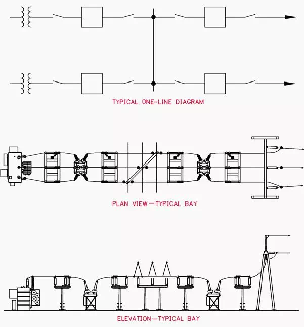 Figure 1 – Single Bus – Low Profile Configuration
Figure 1 illustrates the single bus arrangement with low-profile structures and presents a neat, orderly plan.
The high-profile design, shown in Figure 2, accomplishes the same purpose and may not require as large a site for a given system voltage.
The single bus arrangement is not recommended without circuit breaker bypass facilities that permit circuit breaker maintenance while maintaining circuit operation.
The high-profile configuration can easily be modified to provide this feature by installing group-operated switches and the associated buswork and connections in the positions shown in Figure 2.
This arrangement, however, results in loss of overcurrent protection for the circuit except by remote circuit breakers during the bypassing operations.
A fault occurring on the line with the breaker bypassed would result in complete substation shutdown. The low-profile arrangement does not allow for future addition of this type of bypassing equipment.
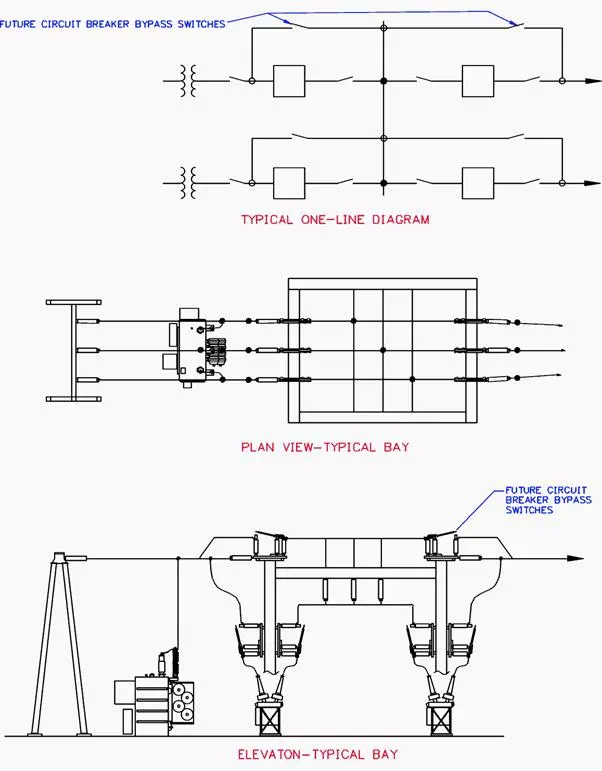 Figure 2 – Single Bus – High Profile Configuration
Consequently, in both low-profile and some high-profile substations, the bypass facilities can be installed outside the substation. Switches can be provided that, when closed, parallel two lines to enable one circuit breaker to be removed from service. The other breaker then protects both circuits.
If this bypassing method is used, the equipment associated with both circuits, have to be capable of carrying the total load of both circuits. If the load is greater than the equipment capability, the load should be reduced.
This method of circuit breaker bypassing may be more desirable in high-profile arrangements than that shown in Figure 2 for lines where frequent or lengthy equipment maintenance is expected.
The high-profile configuration shown in Figure 2 is generally limited to distribution and subtransmission voltage levels. At transmission voltage levels, independent structures and strain bus interconnections are usually used.
Advantages
· Lowest cost.
· Small land area required.
· Easily expandable.
· Simple in concept and operation.
· Relatively simple for the application of protective relaying.
Disadvantages:
· High-profile arrangement equipped with circuit breaker bypass facilities does not provide for circuit protection when bypass facilities are being used inside the substation.
· A single bus arrangement has the lowest reliability.
· Failure of a circuit breaker or a bus fault causes loss of the entire substation.
· Maintenance switching can complicate and disable some of the protective relay scheme and overall relay coordination.
Maintenance at the upper elevations of high-profile arrangements necessitates de-energization or protection of the lower equipment.