Non-linear Op-Amp Circuits
Operational amplifiers, along with linear circuits, are also vastly used to configure non-linear circuits, i.e. circuits whose output exhibits non-linear change with respect to the change in the input. These circuits are commonly known as switching circuits, whose output switches between positive and negative saturation voltage levels. Most popularly used circuit configurations are zero crossing detectors, the Schmitt trigger, astable and monostable multivibrators.
Zero Crossing Detector
A zero crossing detector is the simplest circuit configurations of op-amp switching circuits. In this configuration, the input signal is applied to one of the input terminals while the other input is connected to ground. This circuit needs no feedback connection.
Non-Inverting Zero Crossing Detector
If the input signal source is connected to the non-inverting input terminal of the op-amp and the inverting input terminal is grounded, the circuit is called a Non-inverting zero crossing detector. The circuit diagram is shown in the figure below.
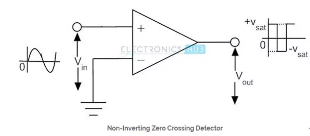
When the input signal is above ground level, the output of the circuit is saturated at its positive extreme. When the input goes below ground level, the output voltage of the circuit immediately switches to its negative saturation level. Every time when the input signal crosses the zero voltage level, the output switches between one saturation level and the other. Since the output of the above circuit goes into positive saturation when the applied input voltage is positive, the circuit is categorized as a non-inverting zero crossing detector. The input and output waveforms of a typical non-inverting zero crossing detector is shown in the above figure. Regardless of the shape of the input wave, the output is always a rectangular wave.
Inverting Zero Crossing Detector
If the input signal is applied to the inverting input terminal of the op-amp, and the non-inverting input terminal is connected to ground, the circuit is called an inverting zero crossing detector. The circuit is shown in the figure below.
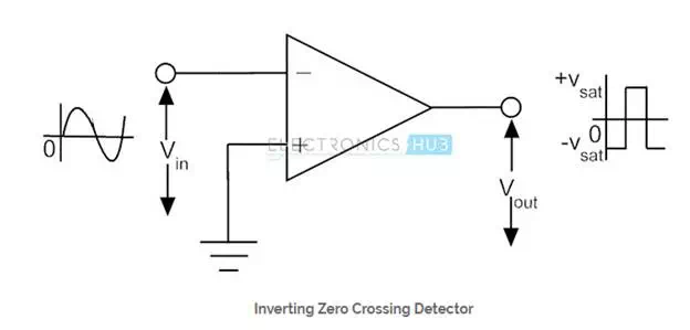
When the input is above ground level, the output is saturated at the negative extreme voltage. When the input voltage goes below ground level, the output immediately switches to positive saturation voltage. Since the output is saturated at negative voltage when the input is positive, this circuit is called as an inverting zero crossing detector. The input and output waveforms of an inverting zero crossing detector is shown in the figure above.