Operational Amplifier as Integrator
Operational amplifier can be configured to perform calculus operations such as differentiation and integration. In an integrating circuit, the output is the integration of the input voltage with respect to time. A passive integrator is a circuit which does not use any active devices like op-amps or transistors.
An integrator circuit which consists of active devices is called an Active integrator. An active integrator provides a much lower output resistance and higher output voltage than is possible with a simple RC circuit.
Op-amp differentiating and integrating circuits are inverting amplifiers, with appropriately placed capacitors. Integrator circuits are usually designed to produce a triangular wave output from a square wave input. Integrating circuits have frequency limitations while operating on sine wave input signals.
Ideal Op-amp Integrator Circuit
An op-amp integrating circuit produces an output voltage which is proportional to the area (amplitude multiplied by time) contained under the waveform. An ideal op-amp integrator uses a capacitor C1, connected between the output and the op-amp inverting input terminal, as shown in the figure below
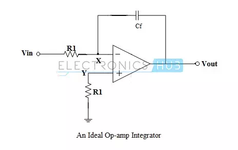
The negative feedback to the inverting input terminal ensures that the node X is held at ground potential (virtual ground). If the input voltage is 0 V, there will be no current through the input resistor R1, and the capacitor is uncharged. Hence, the output voltage is ideally zero.
If a constant positive voltage (DC) is applied to the input of the integrating amplifier, the output voltage will fall negative at a linear rate, in an attempt to keep the inverting input terminal at ground potential. Conversely, a constant negative voltage at the input results in a linearly rising (positive) voltage at the output. The rate of change of the output voltage is proportional to the value of the applied input voltage.
Output Voltage Calculation
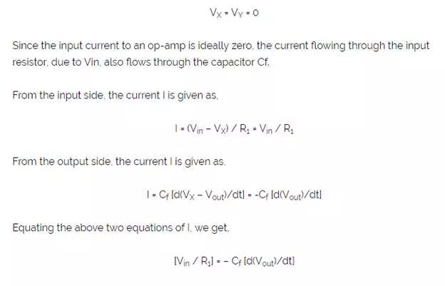
From the circuit, it is seen that node Y is grounded through a compensating resistor R1. Node X will also be at ground potential, due to the virtual ground.
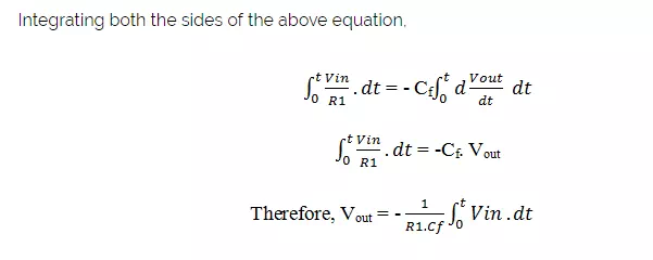
In the above equation, the output is -{1/(R1.Cf)} times the integral of the input voltage, where the term (R1.Cf) is known as the time constant of the integrator. The negative sign indicates that there is a phase shift of 180o between input and output, because the input is provided to the inverting input terminal of the op-amp. The main advantage of an active integrator is the large time constant, which results in the accurate integration of the input signal.