Earth fault protection of Generators
The neutral point of the generator is usually earthed, so as to facilitate the protection of the stator winding and associated system. Impedance is inserted in the earthing lead to limit the magnitude of the earth fault current. Generators which are directly connected to the transmission or distribution system are usually earthed through a resistance which will pass approximately rated current to a terminal earth fault. In case of generator-transformer unit, the generator winding and primary winding of a transformer can be treated as an isolated system that is not influenced by the earthing requirements of the transmission system.
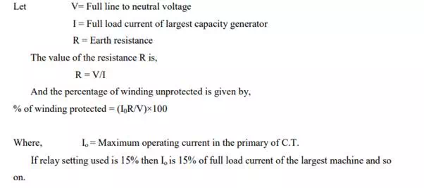
Modern practice is to use a large earthing transformer (5-100 KVA) – the secondary winding which is designed for 100-500V is loaded with a resistor of a value, which when referred through the transformer ratio, will pass a suitable fault current. The resistor is therefore of low value and can be of rugged construction. It is important that the earthing transformer never becomes saturated, otherwise a very undesirable condition of ferro resonance may occur
Earth Fault Protection
Earth fault protection can be obtained by applying a relay to measure the transformer secondary current by connecting a voltage measuring relay in parallel with the load
Generally Merz-Price protection based on circulating current principle provides the protection against internal earth faults. But for large costly generators, an additional protection scheme called restricted earth fault protection is provided.
When the neutral is solidly grounded then the generator gets completely protected against earth faults. But when neutral is grounded through earth resistance, then the stator windings gets partly protected against earth faults. The percentage of windings protected depends on the value of earthing resistance and the relay setting. In this scheme, the value of earth resistance, relay setting, current rating of earth resistance must be carefully selected.
The earth faults are rare near the neutral point as the voltage of neutral point with respect to earth is very less. But when earth fault occurs near the neutral point, then the insufficient voltage across the fault results in a low fault current, that is less than the pickup current of relay coil. Hence the relay coil remains unprotected in this scheme. As it is able to protect a restricted portion of generator winding from earth faults, it is called a restricted earth fault protection. It is usual practice to protect 85% of the winding.
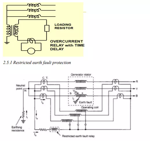
The restricted earth fault protection scheme is shown in the above figure. Consider that earth fault occurs on phase B due to breakdown of its insulation to earth, as shown in the Fig. 1. The fault current If will flow through the core, frame of machine to earth and complete the path through the earthing resistance. The C.T. secondary current Is flows through the operating coil and the restricted earth fault relay coil of the differential protection. The setting of restricted earth fault relay and setting of overcurrent relay are independent of each other. Under this secondary current Is, the relay operates to trip the circuit breaker. The voltage Vbx is sufficient to drive the enough fault current If when the fault point x is away from the neutral point.
If the fault point x is nearer to the neutral point then the voltage Vbx is small and not sufficient to drive enough fault current If . And for this If , relay can‟t operate. Thus part of the winding from the neutral point remains unprotected. To overcome this, if relay setting is chosen very low to make it sensitive to low fault currents, then wrong operation of relay may result. The relay can operate under the conditions of heavy through faults, inaccurate C.T.s, saturation of C.T.s etc. Hence practically 15% of winding from the neutral point is kept unprotected, protecting the remaining 85% of the winding against phase to earth faults.
Let us see the effect of earth resistance on the percentage of winding which remains unprotected.
Consider the earth resistance R is used to limit earth fault current. If it is very small i.e. the neutral is almost solidly grounded, then the fault current is very high. But high fault currents are not desirable hence small R is not preferred for the large machines.
For low resistance R, the value of R is selected such that full load current passes through the neutral, for a full line to neutral voltage V. In medium resistance R, the earth fault current is limited to about 200A for full line to neutral voltage V, for a 60 MW machine.
In high resistance R, the earth fault current is limited to about 10 A. This is used for distribution transformers and generator-transformer units. Now higher the value of earth resistance R, less is the earth fault current and less percentage of winding gets protected. Large percentage of winding remains unprotected.