When 2 Leds Just Don't Cut It Anymore
So far, we've done everything in this series using two LEDs and one button. I'm guessing that the thrill of blinking an LED has worn off by now, hard as that is to imagine. What's more, we've just about reached the limits of what we can learn with such limited I/O. We have come to the point where we need to add some hardware to our setup to continue with additional concepts and microcontroller peripherals.
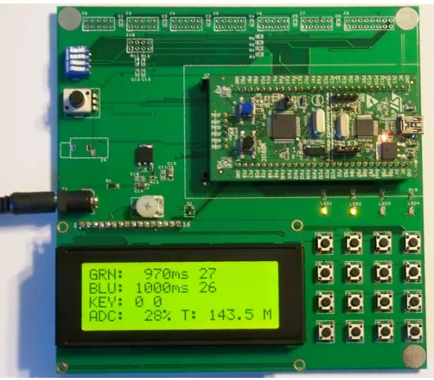
I ran into this problem very quickly after I had picked up my first STM32VLDiscovery board. 32 bit ARM Cortex M3, 128k flash, 8k RAM, timers galore, this was gonna be great! Well, not so much, at least not with the board all by itself. So I designed a docking board with a power source, 4x20 LCD character display, 4x4 button matrix, 4 LEDs, a potentiometer for ADC work, 4 configuration switches, and a bunch of expansion connectors. The STM32VLDiscovery would plug into this board and give a fun and useful system for working with that chip. As soon as I got back the first prototype boards I realized (that being the main function of prototypes, to remind you of things you should have done the first time) I should have added connectors for the STM32F0Discovery, the Cortex M0 version of the Discovery board, so there went a second round of prototypes. Then I decided I could build a board that plugs into the docking board and that holds an ATmega1281, making the docking board useful for Cortex M3, Cortex M0 and AVR training. Here is the result (with STM32VLDiscovery board plugged in):
4 X 20 LCD CHARACTER DISPLAY
These are your common HD44780-compatible displays, available everywhere. I recommend the larger 4x20 displays, but one could use smaller displays such as 2x16. Given the extra information you can fit on a 4x20, I think it is very much worth the few extra dollars for the larger display.
A 44780 display can connect using either 4 or 8 data lines, along with 2 or 3 control lines. I often use the minimalist connection of 4 data lines and 2 control lines, but with a bit more software work the 3rd control line can speed up communication with the display somewhat. If using 4 data lines, the best arrangement is to select the 4 upper bits of a port, e.g. PA4-PA7. The control lines can be any bits on any ports, but it is probably easiest to use the lower bits of the data port. On my docking board I also include a logic-level mosfet to turn the display backlight off and on (and even change its brightness via software or hardware PWM). If you want you can dispense with this output, but then I would suggest wiring the backlight to be permanently ON. Most such displays with their backlights off are very annoying to view, IMO.
4 X 4 BUTTON MATRIX
The button matrix requires 4 GPIO pins that can be configured as inputs and 4 that can be configured as outputs. It is easiest if each set of 4 is contiguous on the same port. Thus e.g. PA1,PA2,PA3,PA4 is preferable to e.g. PA0,PA3,PA4,PA7 (same port but not contiguous), and even more preferable than e.g. PA1, PA3, PB5, PB6 (multiple ports).
Since both the AVR and the STM32 can activate internal pullups on input pins, no external pullup resistors are necessary. If you were working with a uC family that did not have internal pullups, or if you were working in a high electrical-noise environment where lower-value ("stiffer") pullups were desireable for noise reasons, then you would have to add those pullups to each input line.